


|
|
|
Audio equalisation (EQ) for digital organs and virtual pipe organs
"Always be in command of your own music. Only you can control and shape its tone."
Posted: 4 February 2019 Revised: 14 April 2019 Copyright © C E Pykett 2019
Abstract. Digital organs and virtual pipe organs can be disappointing in many ways, but some of the problems can be addressed through the use of audio equalisation (EQ) techniques. For example, the loudspeakers used are often ill-suited to the sounds being radiated in that the original voicing and regulation of an instrument will have been undertaken using entirely different ones. This is particularly true of virtual pipe organs because the same, arbitrary, audio system of fixed characteristics is expected to produce optimum results with any number of sample sets originating from any number of suppliers. This can lead to problems including thin or boomy bass reproduction or excessive brightness in the treble register. Or an organist with age-related hearing loss might find the instrument unsatisfactory towards the top end of the compass, particularly with the higher-pitched stops. Or the use of external effects processors such as reverberation units can introduce spectrum distortions which are immediately identifiable as artificial. Audio equalisation can address all of these and similar problems. Thus a range of equalisation techniques is discussed, including the use of passive or active tone controls and graphic equalisers. All are easy to apply to an existing instrument, and they can be remarkably cost-effective in relation to the benefits which result.
Contents (click on the headings below to skip to the desired section)
PLEASE NOTE - Proprietary items mentioned in this article are for illustrative purposes only and no endorsement of any kind is implied. You use them at your own risk and no responsibility will be accepted for the consequences. Should you proceed with anything suggested in the article it is assumed that you will have the necessary knowledge and experience. You should seek independent advice if necessary.
The dramatic influence of different loudspeakers on audio systems never ceases to surprise me. One can burn up a lot of time and effort in setting up (voicing and regulating) a digital organ or virtual pipe organ (VPO), yet its effect can sometimes be almost destroyed if the speakers are changed subsequently. Often, the extremes of the audio range are most affected, resulting in problems such as either thin or boomy bass, or excessive brightness in the treble. Such problems can arise regardless of the quality and cost of the speakers, and they can also occur with headphones. In an ideal world a commercial digital organ should be sold with exactly the same audio system used by the manufacturer when its stored audio information was originally voiced and regulated before it was brought to market. The same applies to the sample sets for use with VPOs. Yet how often does this desirable state of affairs happen? In fact, how often do you actually know anything at all about the audio mastering processes and equipment used by the manufacturers or the sample set producers? The answer to both questions is "seldom, if ever", thus providing the motivation for this article. And if you use several different sample sets in a virtual pipe organ they will usually have been mastered in different ways and by different people, thus a single speaker system of fixed yet arbitrary characteristics is never going to be optimum for each one.
Further scenarios present similar problems. If an organ is moved into a different room its effect can be modified just as dramatically as if its loudspeakers had been replaced. Or an organist with progressive age-related hearing loss might find the instrument becoming unsatisfactory at the top end of the compass, particularly with the higher-pitched stops. In theory it might be argued that the problems can be solved because most commercial organs and most VPOs allow the user to at least regulate the instrument to some extent by adjusting the volume balance across the compass. Sometimes this can be done on a note by note basis for each stop, and other voicing adjustments might be possible as well. But in practice this can be a tiring and time consuming process which also demands a keen ear and a certain amount of experience, so if you don't like the result it is not necessarily something you can keep repeating until you do. It will also be expensive to ask the supplier to do it for you. So to address all these problems this article discusses the subject of audio equalisation (often abbreviated to EQ) in a generic sense. Applying EQ to an organ might not provide a complete solution in all cases but it will usually improve matters to some extent. Its advantage is that adjustments can be made very rapidly once you have installed the necessary readily-available hardware, which can also be cheap if you elect to use one of the simpler solutions described here. To assist as many readers as possible the article goes back to fundamentals, but if you have more experience then you can of course skip some of the material.
If user-adjustable EQ is already built into a digital organ or VPO it will have been implemented in one of two ways. It can either be done digitally within the software of the computer-controlled sound engine used by the instrument, or alternatively there might be physical EQ control knobs or adjustable presets in the analogue signal paths feeding each power amplifier. Obviously it is only possible to retrofit the second type to an existing instrument not having variable EQ, aside from the rare occasions when a user has access to the source code of the software and is competent to modify it. Consequently the article only discusses analogue EQ techniques in what follows, though these are by no means out of date as they are still used widely today in audio engineering.
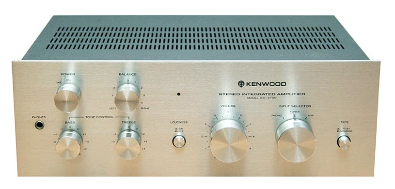
Conventional audio tone controls are a simple but nevertheless useful form of EQ for organ work. They are also probably the cheapest option. An example is the bass and treble lift/cut controls which once featured in almost every hi-fi system, though they are less common today. One comes across various grandiose reasons for this, such as the alleged undesirability of passing audio signals through too many processing stages, or an insistence that you should have to listen to the sounds "as recorded". That's not much different to saying that you shouldn't be allowed to adjust the seats in your car. However let's be clear that the main reason for their absence in today's cut throat market is actually that of pruning prices to the bare bones minimum. But because tone controls are now thinner on the ground it is unfortunate that recent generations of audiophiles and musicians are, by and large, less familiar with these useful accessories than were their forbears. Consequently we shall look first at the background to old fashioned tone controls because it is cheap and relatively easy to add them to each audio channel of a digital organ if you have some basic electronics experience. However, before incorporating them permanently you can try their effect fairly readily on just one or two audio channels of your instrument by temporarily driving the associated loudspeakers with an 'integrated' stereo amplifier instead of the amplifiers built into the organ. This will often be an older unit having built-in (i.e. integrated) preamplifiers complete with tone controls. If you don't have access to one, amplifiers of this vintage turn up on the pre-owned market all the time. The Kenwood (aka Trio) KA-3700/50 shown in Figure 1 is one of many still-popular examples suggested at random if you are unsure what to look for, and several were being offered on eBay as I wrote this. (The two versions differ only in their appearance and finish as far as I know). Whether you do this experiment or not, if you then go on to construct or purchase a number of tone control units the following background might be useful.
Figure 1. Kenwood (sometimes badged as Trio) KA-3700 amplifier. The KA-3750 was similar but with a grey panel.
Let us first hark back to the 1950's. This remains relevant today because we are going back to the days of high quality valve (tube) amplifier designs such as those by Mullard, still widely used by 'valve' audiophiles. They used tone controls which were often based on what was called a James network [1].
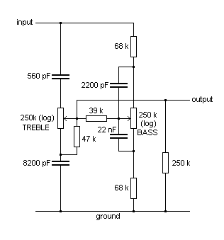
Figure 2. A James passive tone control network
Illustrated in Figure 2, this is a purely passive network which therefore does not include an active device such as a valve, transistor or IC. Each control provides lift or cut depending on the direction in which you turn the knob away from the centre position. Its (approximate) frequency response is shown in Figure 3, in which the line slopes do not exceed 6 dB per octave up or down. It works quite well and I have built several of them in my time for power amplifiers such as the Mullard 5/10 (the one with EL84 output valves), which specified James tone controls as part of the original design.
Figure 3. Typical tone control response curves
However the James network introduces a significant mid-band insertion loss (attenuation) of typically 20 dB or a factor of 10, the exact figure depending on the component values. This is necessarily so, because if you are to get a certain amount of boost at the extremes of the band using only a passive network which has no gain, then obviously the network has to attenuate the mid-band signal by the same factor. Fortunately some of the Mullard power amplifiers were too sensitive for many applications, thus the insertion loss of the James network at the front end was an advantage when matching them to a preamplifier or directly to some signal sources. This was true of their 5/10 design for example. However lower-gain amplifiers required an extra gain stage to compensate for the losses in the tone network. Another issue, though not really one of much consequence, is that the treble and bass controls interact to some extent. And if you are into Laplace Transforms, an analysis of the James network will show you what a clever guy he was considering he had no computer to help him in those days.
Some practical points are that the network should be driven from a relatively low source impedance (say below 15 kohm) and terminated in a relatively high impedance (around 1 Mohm). It should also be completely enclosed in an earthed (grounded) metal enclosure to prevent hum pickup.
Active (Baxandall) tone controls
A few years after Mr James wrote his article [1] along came Peter Baxandall, who was an electronics engineer then working at the former Royal Radar Establishment in Malvern, England. Noting that the passive James network sometimes needed gain from a valve somewhere in the system to compensate for its attenuation, he saw that its performance could also be improved in other respects by configuring the valve as an operational amplifier rather than merely as a signal booster. Valve op-amps were being used in the analogue computers which were a hot topic of the day, and the tone network then became an active rather than a passive filter. Thus Baxandall's tone control used much the same James network, but it was placed in the feedback loop around an active device - originally a single pentode valve [2]. One of the advantages conferred by this arrangement was that interaction between the treble and bass controls was eliminated, another was that the gain of the op-amp compensated for the attenuation of the network, and yet another was that linear rather than lower quality logarithmic potentiometers could be used. The circuit also became symmetrical in terms of the 'lift' and 'cut' capacitor values. Baxandall's tone control article of 1952 [2] helped to catapult him to fame in audio engineering to the extent that he took early retirement in the 1970s to become an independent audio consultant.
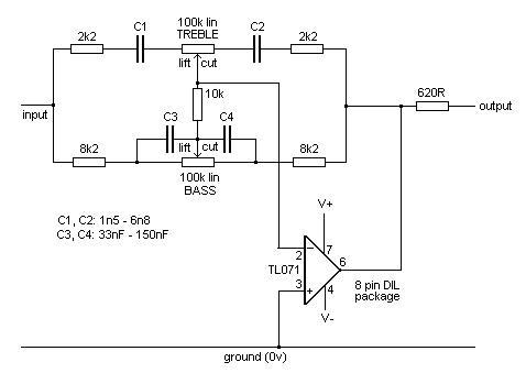
Today most of us build op-amp circuits using ICs rather than valves, and a suitable Baxandall-type tone control circuit is shown in Figure 4. Few if any practical designs have been identical to Baxandall's original in every respect, which among other things required a treble potentiometer with a centre-tapped track - a rare item today. Not everyone seems to realise this.
Figure 4. A Baxandall active tone control network
The value of C1 should equal that of C2 and C3 should equal C4 regardless of the values chosen so that the lift-cut symmetry of the circuit is not disturbed. The op-amp can be a 741, although better noise performance and distortion figures will be obtained with devices such as a TL071. The 620 ohm snubbing resistor at the output helps to suppress the inclination of some op-amps to go into parasitic oscillation if loaded capacitively, such as when connecting a screened lead to the output. This oscillatory tendency is not helped by the potentially gross and unpredictable phase shift and attenuation which the tone network introduces across the op-amp as it is adjusted by the user. Thus an unconditionally stable op-amp must always be used, and this cannot be emphasised too strongly. Ultrasonic parasitic oscillation can wreck a power amplifier without you knowing anything about it until you see and smell the smoke.
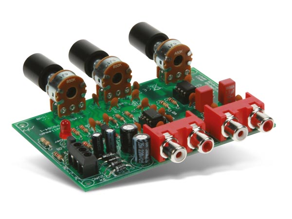
Cheap Baxandall tone control modules are widely available commercially at the time of writing (2019) e.g. the Velleman K8084 unit (Figure 5). Each of these will control two audio channels.
Figure 5. Velleman K8084 2-channel volume and EQ control module
Variable corner frequency (Linsley Hood) tone controls
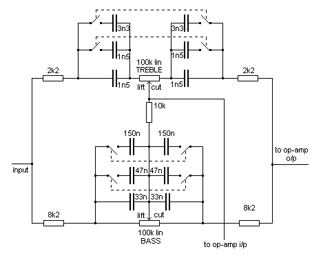
It can be useful to shift the corner (mid-band) frequency of tone controls away from the common value of 1 kHz because it is often only the extremes of the frequency range which need to be adjusted. The shifting is done by choosing alternative capacitor values, which results in the response curves in Figure 3 being slid bodily along the frequency axis to leave a horizontal portion in the middle. Typical values are given in Figure 6, and it is useful to have a few capacitors permanently wired in and selected by switches as shown. This arrangement was used by John Linsley Hood in some of his well known hi-fi amplifier designs of the 1970s and 80s, and it is also valuable for organ work.
Figure 6. Linsley Hood's capacitor switching arrangement
Each switch is a physically independent latching (push-on/push-off) button, therefore the number of possible values of capacitance is four for each control. Corresponding switches are ganged to maintain symmetry (equality of capacitance values) in a simple manner i.e. there is a total of four double pole push buttons shown in the diagram, each one switching two identical capacitance values.
The corner frequency of the treble control is thereby made selectable in four discrete steps from 1 kHz up to 7.5 kHz. With all capacitors in circuit, i.e. with all the switches closed, the corner frequency is about 1 kHz. As capacitors are removed by opening the switches, it moves upwards in frequency. Therefore the push buttons are wired so they disconnect the capacitors when pressed.
The corner frequency of the bass control is selectable in four steps from 1 kHz down to 100 Hz. With all switches open the corner frequency is 1 kHz. As capacitors are added by closing the switches, it moves downwards in frequency. Therefore the push buttons are wired so they connect the capacitors when pressed - the reverse of the treble switching circuit.
Not shown in the diagram are twelve high value resistors, typically 3M9, one connected across each capacitor to prevent clicks and thuds when the switches are operated. Not essential but a nice touch. In Figures 4 and 6 it is assumed that no DC is present on the input signal, and that the ground-referred output can be connected directly to a power amplifier. If neither of these applies then suitable DC blocking capacitors must be included.
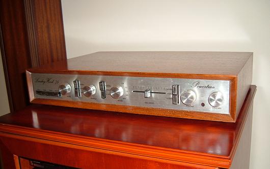
Besides the variable corner frequencies, another noteworthy feature of Linsley Hood's tone control circuit was the use of an op-amp made up from three discrete transistors rather than using the lower performance ICs then available. He referred to this design as the 'Liniac' (linear inverting amplifier circuit) [4]. With its several Liniacs, his celebrated high performance 75 watt integrated hi-fi amplifier [3] used only discrete transistors throughout, thereby making it resistant to obsolescence in that it could easily be repaired. I made one from a kit around 45 years ago and it is still going strong - see Figure 7. The push buttons for the bass and treble controls are the two vertical pairs left of centre. Another pair is also used in a variable 'scratch' filter towards the right side - useful when playing vinyl and (particularly) 78 rpm source material.
Figure 7. 75W integrated stereo amplifier by J L Linsley Hood (Powertran kit)
Graphic equalisers are considerably more complicated than the simple tone controls discussed so far, and they also work in a completely different way. For a start, the tone controls described above use either high pass or low pass filters, whereas in a graphic equaliser the filters are of the band pass variety. The audio frequency band is spanned by a relatively large number of them, typically 15, and each provides variable lift or cut independently of the others. By using slider potentiometers rather than rotary ones, the positions of their control knobs then represent a coarse but useful graphic display of how the audio spectrum is being modified, hence the name. Details of the filter circuits are not given here as they are widely described on the web, and in any case several different techniques are in common usage. The bandwidth of each filter is related to the total number employed in that the complete set has to cover the range of human hearing, about ten octaves. Thus an equaliser with 15 filters would require filter bandwidths of two-thirds of an octave, because 15 times 2/3 equals 10. This bandwidth is equivalent to a frequency span of 8 semitones, the same as a musical interval of a minor sixth or a frequency ratio of 1.5874. Thus the centre frequencies of adjacent filters are also separated by the same amount. The frequency response of each filter in a graphic equaliser is therefore fairly broad, which means that they cannot compensate sensibly for the much narrower peaks and troughs which occur with particular loudspeakers in particular rooms as often supposed. Instead, they are intended for overall tone compensation across relatively broad bands in a convenient and user-friendly way rather than cancelling specific room modes or loudspeaker resonances, although they might sometimes tame such problems to some extent. For the same reason graphic equalisers cannot compensate for particular notes on a digital organ which might be too weak or too pronounced, since a range of other notes on both sides of the culprit will also be strongly affected. They are more suitable for doing things like boosting the lowest half-octave or so on the pedals where loudspeakers become less effective, rendering screaming mixtures and mutations more docile higher in the key compass, or compensating for age-related hearing loss towards the top end. They can also reduce the spectrum distortions introduced by effects modules such as reverberation units, thus making them sound less artificial.
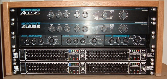
In view of their complexity it is unrealistic to contemplate the construction of a graphic equaliser with more than a few filters, thus they need to be purchased. At the time of writing (2019) retail prices start from about 100 GBP in the UK for a two-channel (stereo) unit. They are therefore far more expensive than a typical tone control module of the Baxandall variety, though they offer more flexibility. It is unwise trying to keep costs down by buying used items without testing them thoroughly first. This is because random failures tend to arise in particular frequency channels over time in view of the large number of discrete components. If you do contemplate a pre-owned item you should focus particularly on noisy potentiometers as dismantling a unit for repair can be physically very tricky, even assuming you can source new components which are drop-in replacements. Another potential maintenance problem is that most of the components on the PCBs of a modern unit are microscopic surface-mount devices. Nevertheless I have found graphic equalisers very useful over some years on my Prog Organ virtual pipe organ which uses many different sample sets. It is unrealistic to expect each sample set to necessarily give of its best using a sound system of fixed characteristics, and in any case one sometimes likes to experiment with a bit of EQ for other reasons or just for its own sake. So I have incorporated a pair of commercial graphic equalisers (accommodating four audio channels) which sit on top of the console. This enables adjustments to be made quickly if necessary when a new sample set is loaded. A picture of my signal conditioning and effects setup is shown in Figure 8 in which the graphic equalisers are the lowest pair of the 19-inch rack modules. (The other modules are for purposes not connected with this article).
Figure 8. Signal conditioning and effects rack used in the Prog Organ virtual pipe organ
These items are type GE215 marketed by L2 Audio which were available from a number of outlets when I bought them some years ago, though I suspect they were much the same Chinese product as those rebadged for other suppliers at the time. They are very feature-rich as follows:
Rotary control for overall gain
1. "Simple Tone Control Circuit", E J James,
Wireless World, February 1949.
|