


|
|
|
The Electromechanical Combination Capture Systems formerly used in Pipe Organs
by Colin Pykett
Posted: 11 June 2012 Last revised: 5 January 2015 Copyright © C E Pykett 2012-2015
"Every time I went into the studio some engineer tried to impress me with how they're going to capture my sound with all kinds of tricks. But they limited the sound and never allowed me to play how I felt" Dick Dale
Abstract. A number of electromechanical combination capture systems were introduced by various organ builders in the 1930's and they continued in use for nearly half a century. This article surveys three representative systems - those of Willis III, Compton and Hill, Norman & Beard. Willis's was one of the earliest, with a design clearly based on the simple manual setter board - an automatic memory and switching element replaced each manual switch in a setter board of the same size. Although the system was conceptually simple, the requirement for a very large number of magnetically-operated memories made it cumbersome and probably rather expensive. Compton developed a system which required far fewer magnets, though at the expense of greater mechanical complexity. His system was also based on the orthogonal arrangement of a setter board with its rows and columns, but it addressed each switching intersection indirectly via its co-ordinates in the matrix. HN&B adopted a similar though thoroughly re-engineered system some years later.
These and similar systems held the field until the 1970's, when they were displaced by electronics. Although they showed evidence of considerable design and manufacturing skill, they all suffered from a major shortcoming - they only captured one setting at a time, thus they only had a single memory level. The introduction of electronic memories did away with this problem at a stroke. However the old systems were eminently maintainable and repairable, and that in Compton's organ of 1937 at Southampton's Guildhall has recently been refurbished after nearly 75 years' service. No electronic system can possibly compete with this, dominated as they are by limited life partly due to rapid obsolescence.
The article is intended to document the details of these systems for posterity before the limited information available slips away for ever.
Contents (click on the headings below to access the desired section)
In the Beginning was the Setter Board
Hill, Norman and Beard's Capture System
The idea of quickly capturing a combination of organ stops which can then be recalled at will goes back well into the nineteenth century. The usual arrangement, at least on British and American organs, is first to arrange the desired combination to be captured on a particular piston. Then a setter button or piston of some sort is pressed and, while keeping it pressed, the required combination piston. Finally these are released in the reverse order, leaving the combination captured on the chosen piston. These earliest 'capture systems' arose in about 1882 with an all-mechanical system invented by Roosevelt in the USA, though this was not quite of the type just described. It had a number of tilting tablets associated with each drawstop, each one corresponding to the setting of that stop (on or off) desired for the related combination pedal. Thus the array of tablets was equivalent to a mechanical setter board, but because they could be manipulated while seated at the console it seems reasonable to regard it as a close approach to what we would call a capture system. However a few years later, in 1889, Duval in Canada presented his fully adjustable system which was probably the first to have a 'setter button' (actually it was a pedal). This too was a fully mechanical system, though one of considerable complexity, elegance even. A pneumatic variant of Duval's system was developed by Wirsching of Ohio in 1892, and thereafter the flood gates opened with many builders incorporating their own variants of the pneumatic combination capture principle. In recent years the pneumatic capture system of the large 1909 Binns organ at the Albert Hall, Nottingham was returned to full working order in a comprehensive restoration by Harrison and Harrison. This verges on the unique, because old capture systems have for many years been universally discarded in favour of electronically controlled stop control schemes when organs are rebuilt.
In parallel with the application of electricity to other aspects of organ actions, electric variants of these pneumatic capture systems also appeared, first using electropneumatic mechanisms and later fully electric ones. The tardier appearance of the latter was because of the relatively greedy power requirements of an electromechanical as opposed to an electropneumatic system at a time when the problem of providing sufficient DC power at low voltage for organ actions was still causing headaches for organ builders. Not surprisingly, Robert Hope-Jones was among those who advanced the state of the art in this field, particularly during his sojourn in America between 1903 and 1914. This article describes in detail some examples of the ultimate embodiments of these fully electric (i.e. electromechanical) capture systems which were developed in England by three firms during the first half of the twentieth century: Henry Willis III, John Compton and Hill, Norman and Beard (HN&B) . They remained in exclusive use until about the 1970's, when systems using electromechanical components were then progressively displaced by electronic ones (in particular those incorporating computer-type memories). Although many other organ builders used their own systems, such as Wicks in the USA, the three types of mechanism to be described are reasonably representative of the wider scene once it became technically stable and mature prior to 1950. That in the 1937 Compton organ at the Guildhall, Southampton was restored recently by HWS Associates and it is described in detail later. Like the pneumatic system at the Nottingham Albert Hall, this is now one of the very few electric systems from its era to remain at all, let alone one in full working order.
As far as I am aware no account comparable to this article exists elsewhere. Thus the reason for writing it was so that the details of these fascinating systems are made available to a wider audience before they become lost to all but a few.
In the Beginning was the Setter Board
Before diving into the details, which can be a decided challenge to unravel, let us begin with the simplest form of adjustable combination system using a manual setter board. Although a setter board is not a capture system in the sense used here, even these are not quite as straightforward as they might appear if the correspondence I receive is anything to go by. Not infrequently I get requests for circuit diagrams to enable people to make up their own systems, or to assist them in repairing or modifying existing ones. (Organ builders, of course, can skip this bit!).
Figure 1. Combination system using a manual setter board
A schematic diagram of an electric combination action using a setter board accommodating N pistons and M stops is shown at Figure 1. It consists of M pairs of busbars, one pair for each stop. One busbar of each pair is connected to the ON magnet of its corresponding drawstop or stopkey, and the other is connected to the OFF magnet. The M pairs of busbars are stacked vertically in the diagram, though only two pairs are shown for simplicity.
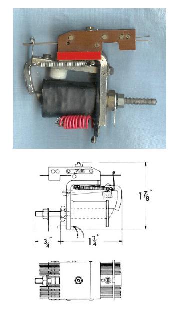
Each pair of busbars is connected to N two-way switches, also known as changeover or single-pole double-throw (SPDT) switches. They are arranged horizontally in the diagram, and again only two are shown for each busbar-pair. These are the switches which are set manually by the organist to retain his or her stop combinations. The common contact of each setter switch is routed to the DC supply through another switch operated by its associated piston. Thus each piston closes M contacts when it is operated by the player. When it does so, each stop goes ON or OFF depending on how the setter switches have been arranged. If a particular stop is already in the correct state, nothing happens to it apart from an extra shove to keep it there. In the diagram the M contacts for each piston are shown as though the piston operates them directly through some form of mechanical linkage. This can indeed be done and the method was sometimes used by builders including Hope-Jones and Willis III, though it was (and is) more usual for the piston itself to operate a relay which then closes the requisite number of circuits. This is more convenient to the organ builder when he is wiring up the system, in that the piston itself (hidden within the depths of a keyboard) then only has to close a single contact which controls the relay coil. A combination action relay which has been in use in the UK for well over half a century is shown in Figure 1, and the fact it is still easily obtainable shows that electromechanical combination actions are still popular with organ builders (and there's nothing wrong with that I might add). The firm which markets this item (Kimber-Allen UK Ltd) also supplies the other components needed to make up a setter board, including small setter switches.
Figure 2. A multi-contact piston relay for electromechanical combination actions (courtesy Kimber-Allen UK Ltd)
Thus a setter board consists of a matrix of manually operated setter switches organised as M rows by N columns (M is the number of stops and N the number of pistons). In today's jargon the board is a PROM (Programmable Read-Only Memory) with a capacity of MN bits (binary digits). To go further and turn it into a capture system it is necessary that the switches are operated automatically on the command of a setter button, rather than being pre-set manually. This converts it into an EEPROM (Electrically-Eraseable Programmable Read-Only Memory) which can not only be read when a piston is pressed, but it can also be written into when the setter button is operated. But how can we achieve this?
One way to do it would be to replace each setter switch with an ordinary relay, each one having a changeover contact. By suitably wiring the system, some or all of the relays would change state depending on the combination to be captured when the setter button was pressed. Some relays would then remain set when the button was released while others would not, to mirror the captured combination. This would be fine except for one major drawback - all the settings would be lost when the organ power supply was turned off, because those relays which were set would lose power to their coils. When it was next switched on, the combination on each and every piston would either be all stops OFF or all ON depending on how the system had been wired. The system would have suffered total amnesia. Therefore this suggestion is unworkable. Some other form of electrically-operated switch has to be devised which retains its setting - ON or OFF - for an indefinite period regardless of whether it is powered up or not. The search for a reliable and reasonably economical non-volatile memory element is therefore the nub of the issue, and it dominated the efforts of those trying to implement the first electromechanical capture systems nearly a century ago.
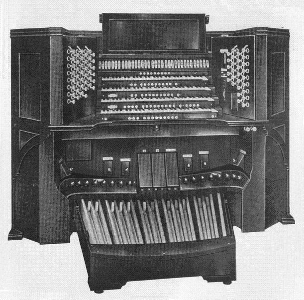
By the 1930's Henry Willis III, the grandson of the illustrious founder of the dynasty, had more or less standardised the consoles used in his organs with electric action (Figure 3). Often detached, they became deservedly well liked by organists on account of their handsome and standard layout and comfortable playing experience. They often incorporated a fully electromechanical capture system, and the setter button on the console shown in Figure 3 is that at the left hand end of the lowest keyslip.
Figure 3. A four manual detached console by Henry Willis III (1933)
The brains behind much of Willis's electrical designs at this time were largely those of Aubrey Thompson-Allen (1907-1974). Taken on as an apprentice, he ultimately became managing director before leaving to found a firm in America which bears his name to this day. Prior to this it is likely he had gained intimate knowledge of the latest technical developments in organ building on both sides of the Atlantic, as there is evidence of cross-fertilisation between Willis's practices and those of firms such as Aeolian-Skinner which was led by another Willis emigré, G Donald Harrison. Thompson-Allen's engineering legacy reveals considerable design flair, and if he did not originate all of it himself then the firm must have imported it in one way or another from others with similar talents. Among other things, he invented the 'Infinite Speed and Gradation' method of swell shutter control which I have described in detail elsewhere on this website [1].
Thompson-Allen developed the Willis capture system which was entirely electromechanical and self-contained within a console of the type shown in Figure 3. Technically, its most important element was a non-volatile memory unit capable of storing the setting (ON or OFF) of one stop for one piston. Therefore in a single department of an organ (e.g. the swell organ) which had 16 stops and 10 pistons there would be 160 such units. A comparable memory bank would have been necessary for the other departments, and for the general pistons which operated on the entire organ. In addition, yet further units would cater for separate pedal combinations associated with the manual pistons. Therefore there would be at least several hundred memory units in most instruments, exactly the same as the number of switches in an equivalent manual setter board had one been used. Thus it is interesting that the architecture of Thompson-Allen's capture system closely followed the simple concept outlined above in which each memory unit was, in effect, an automatic changeover switch situated at each node of an orthogonal setter board matrix. This suggests that he followed the same train of thought when designing it, starting from the simple manual setter board and ending with a fully automatic version of it. This did not lead to the most economical system in terms of numbers of switches, contacts, magnets and wiring, but it possessed other advantages. One was that the only specialised component involved was the memory unit itself. Although this was required in large numbers, this meant that it could be mass-produced relatively cheaply. And because everything else in the system was standard, it could be assembled by anyone with sufficient patience and no more skill than that necessary for wielding a soldering iron (i.e. the cheap labour extractable from a long-suffering apprentice). Moreover, the system was reasonably maintainable and repairable on account of the simplicity of its basic design.
Figure 4. Willis III's electromechanical combination capture system designed by Aubrey Thompson-Allen c. 1930 (corrected version)
Figure 4 shows the essentials of Thompson-Allen's electromechanical capture system for one stop and one piston. The memory unit referred to above is contrived from the items labelled G and D, consisting respectively of a small double-acting solenoid with two electrically independent windings (i.e. no common connection) operating a sliding changeover switch. Note that the importance of independent coils is not immediately apparent from the sketch. The changeover switch D will remain indefinitely in the position it adopted when the setter button was last operated, regardless of whether the organ is switched on or not, therefore the memory is non-volatile as required. The drawstop is moved by two separate solenoids, not a single double-acting one as is usual today, and it operates a two-way (SPDT) switch with contacts E and F at the rear. The piston is shown controlling multiple circuits directly at C, rather than via a relay. The setter button (not shown) operates switches A and B (actually these are relay contacts), and the states of these contacts in the diagram correspond to the setter button in its released position.
Unfortunately there were some wiring errors in the original version of this diagram, so the system as depicted in early patents would not work. This is an endemic problem afflicting many illustrations in patent specifications, and some circuits devised by Hope-Jones as far back as the 1890's are similarly affected in their printed versions. One wonders whether this was deliberate. In the present case, the errors have been uncritically propagated by every author known to me who has faithfully reproduced the original version of the circuit, including dear old Sumner [2]. One could have expected better of someone with a physics degree, though his book does rather demonstrate the evanescence of his critical faculties whenever Willis's name was mentioned.
I have corrected the circuit as presented in Figure 4, so let us see how it works. With switches A and B in the positions shown, the system reads the state of memory switch D when the combination piston is pressed, and this activates the corresponding solenoid of the drawstop unit. In this case the drawstop would therefore be thrown OFF. Note that the circuit in this read-out or recall state is exactly the same as that of the simple manual setter board shown earlier in Figure 1. However, when the setter button is pressed the memory is placed into 'write' rather than 'read' mode by the closure of switch B. Simultaneously, switch A opens to prevent power being applied to the drawstop solenoids. In the circuit as depicted in which the drawstop is OFF, power will then flow through the OFF winding of memory solenoid G when the combination piston is pressed, and if its associated switch D happened to be ON it would therefore move to the OFF position as required. This setting would then be captured indefinitely when the piston and setter button were released.
The system is therefore fairly straightforward in concept, but it is not economical in terms of the number of switches and contacts employed. In particular:
1. The drawstop has to operate a SPDT switch rather than a simpler SPST one.
2. Three contacts of the piston contact stack C have to be allocated to each stop. One of these is for operating the appropriate drawstop solenoid in recall mode, with the other two used for setting the state of the memory switch D when the setter button is activated. The number of contacts required per piston is therefore potentially very large, especially if the piston in question is a general one acting on the entire organ. This casts doubt on whether it would have been practical for these contacts to have been operated directly by the piston as shown in the diagram, and a more sensible scheme would have been for the piston to operate one or more relays of the general type shown in Figure 2. It would also have invited early failure if the total current to all solenoids in the system were to be supplied via a single contact in stack C, as shown in the diagram. Such currents would have been in the region of several tens of ampères for a general piston, resulting in rapid erosion prior to total evaporation of a single wire contact. Therefore the piston contact arrangement sketched at C might have been for illustrative purposes only, although Willis did use this method from time to time in less demanding applications.
3. The setter button activates switches A and B, which are in fact operated by separate steering relays. One relay (corresponding to A) requires as many normally-closed contacts are there are stops to be controlled. That corresponding to B requires twice as many normally-open contacts as stops to be controlled. Because each department of the organ plus the general pistons require their own set of steering relays, all activated by the setter button, this is far from a trivial requirement which has to be included within the context of the system as a whole.
4. The number of memory units (D plus G) equals the number of stops to be controlled multiplied by the number of pistons. This also is a large number in an organ of any size.
Examination of the circuit shows some economies could have been made, and perhaps this was done in later versions of the system. However I have enough personal experience of Willis organs from that era to be able to say that it did work, at least it worked well enough. In particular, I played the large three manual organ (1932) at King's College, London frequently over several years and I do not recall the capture system being unreliable. If anything it was the drawstop units themselves which gave most trouble to the player. Because there was no toggle or detent action in the mechanism, sometimes they would not move fully on or off, especially if the pistons were prodded too quickly. Also the pressure between the contact wires and wiper bar at the rear was simply not great enough to render them fully reliable over long periods, and it was not possible to stiffen the contacts because this would worsen the already unsatisfactory mechanical properties of the drawstop itself. However none of this was anything to do with the capture system per se. One of its rather endearing features was a satisfying and tactile thump from within the console when you set a new combination, particularly on a general piston. It told you that something had definitely happened inside!
John Compton evolved a fully electromechanical capture system at about the same time as Willis III, but its concept was entirely different. In Willis' system each stored bit could be addressed individually, even though this degree of flexibility was never needed nor used. This is because one never needs to access individual bits in a combination system - information can always be written to and recalled from a combination memory in chunks corresponding to the several stops associated with a given piston. This is similar to today's electronic memory chips which are byte-addressable rather than bit-addressable - whenever the memory contents is accessed, you have to do it by reading or writing bytes (groups of bits) rather than the individual bits themselves. This has become so universal in computer technology today that it never provokes a moment's thought..
When writing this article in 2012 I did not know who realised this on behalf of Compton in the 1930's, but Colin Mitchell has since drawn my attention to a patent taken out by J I Taylor on behalf of Compton's in 1935 [3]. Mr Mitchell also surmised that A H Midgeley, a director at the firm who had a close working relationship with Taylor, might also have had a hand in designing the system. The concept enabled significant economies to be made in terms of the number of magnets required in the memory, though it was probably less easily assembled, maintained and repaired than was Willis's system. Like the simple setter board and Willis's scheme, its memory switches were placed at the nodes of a matrix whose rows represented stops and the columns pistons. However the switches were mechanically ganged together and operated simultaneously in groups, both on a row and a column basis. It was not possible (nor necessary) to address an individual memory element in the same way that Willis's system allowed in theory; rather, each switching and storage element was addressed by activating the two magnets corresponding to its row and column co-ordinates. The arrangement led to the economies just mentioned: instead of requiring MN electrically-addressable memory units with individual magnets (M = number of stops; N = number of pistons), Compton's system only required M + N magnets to address the same memory of MN bits, a much smaller number of magnets particularly in large organs.
Surviving examples of Compton's capture system are exceedingly rare, and I must therefore acknowledge my gratitude for information provided by HWS Associates who recently refurbished the electromechanical capture system in the organ at Southampton's Guildhall (1937). This is a very large instrument with two consoles, the classical one (called the 'concert console') fitted with Compton's luminous touches and the theatre-style one (the 'variety console') fitted with standard motorised stop keys. The information in what follows has been very kindly provided by Lucien Nunes who played a major role in the refurbishment.
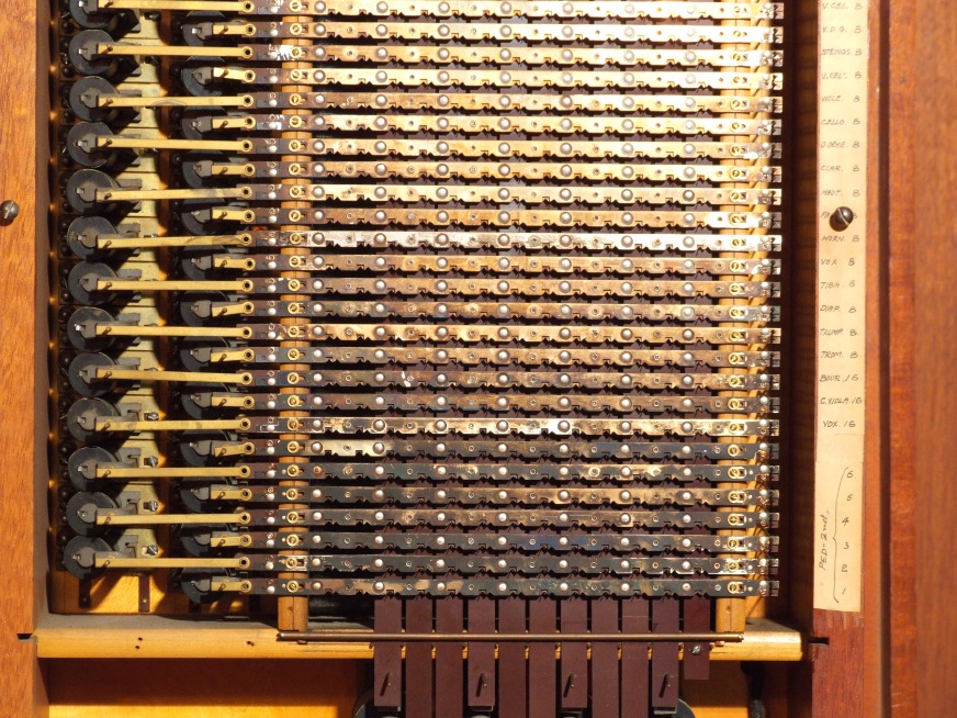
Each department in both consoles of the organ uses a separate memory and recall unit called a 'selector'. Data are written and recalled using two physically separate switching assemblies mounted back-to-back, and a picture of one of the 'write' data storage mechanisms is shown in Figure 5.
Figure 5. One of the capture system storage 'selectors' in Compton's organ at the Guildhall, Southampton (1937) (© Lucien Nunes)
Each stop of this department is associated with one of the lever magnets stacked vertically on the left of the diagram, and each piston is associated with another set of magnets arranged horizontally at the bottom (almost out of shot but they can just be discerned). The heart of the storage mechanism is the horizontal slider operated by each stop magnet. Data are stored at each row-and-column intersection of the matrix using contact wires which are automatically located in ON or OFF notches cut into the sliders when the magnets are energised, although the wires cannot be discerned easily in the picture. However their arrangement and function will now be described.
Figure 6. Illustrating the contact sliders in Compton's capture system
Figure 6 is a sketch illustrating the construction of the horizontal contact sliders and how they interact with the contact wires. Each slider consists of a 3-layer sandwich, with conducting nickel silver strips on each face of a central paxolin insulator. The sandwich is riveted together in a manner which does not compromise the electrical isolation of the two metal strips (the rivets are not shown in the diagram for clarity though they can be seen in Figure 5). One of the strips is connected to the ON magnet of its associated stop mechanism, and the other is connected to the OFF magnet. The plan view shows how pairs of adjacent notches are cut into the metal strips, one notch in the top surface (shown red) and the adjacent one of the pair in the lower surface (blue). The top surface is physically cut away above each notch in the lower so as not to interfere with the contact wire protruding through it, as shown. The number of notch-pairs equals the number of pistons handled by the selector unit. For each slider, sprung contact wires running perpendicular to the plane of the diagram, one wire per piston, take up positions either in the ON or OFF notches depending on the combination last set, and the manner in which this comes about will now be described.
When the setter button is pressed, the sliders for all stops which are ON move to the left under the influence of their respective lever magnets. The contact wires bend with them without leaving their notches at this stage. Sliders for stops which are OFF do not move. When a combination piston is pressed (while keeping the setter button pressed also) its lever magnet at the bottom of the selector assembly pulls all of its contacts wires clear of the notches they previously occupied, and they then become vertically aligned as a result of their springiness. When the piston is released again, each wire drops into an ON or OFF notch depending on whether or not the corresponding slider had moved to the left earlier. When the setter button is released, all sliders revert to their right hand position, leaving the wires in the notches they have just occupied and thereby capturing the combination for the chosen piston.
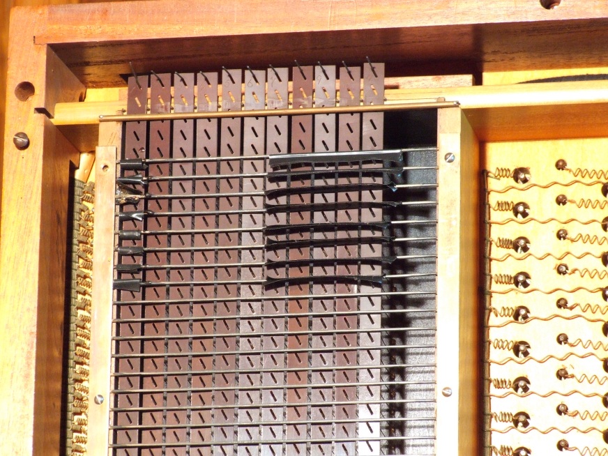
Figure 7. Compton's capture system - recall mechanism before refurbishment (© Lucien Nunes)
The captured data are recalled by a separate mechanism on the rear of the selector system just described. Basically this mechanism is merely a set of piston relays, electrically identical with but mechanically different from the relays discussed earlier and illustrated in Figure 2. The contact wires from the memory selectors pass through a wooden separating panel and then through holes in a set of vertical paxolin traces as shown in Figure 7. Each trace is pulled down by a lever arm magnet at the bottom of the assembly (not visible in the picture) when a combination piston is pressed. When this happens, all wires are brought into contact with a grid of horizontal busbars which are all connected to the power supply. Therefore current flows from the grid, through the wires and into the notches in the selector sliders which are connected to either the ON or OFF stop action magnets. By this means the combination previously captured for that piston is recalled. The picture at Figure 7 was taken before dismantling and refurbishment had been completed, which accounts for the presence of bits of insulating tape on parts of the grid. (Mr Nunes explained that these were added so that certain stops on certain pistons would not be controlled by the pistons and so would remain 'neutral').
As with Willis's scheme, a number of steering relays are used to switch between the 'read' and 'write' modes of the system but these will not be discussed further.
The capture system in this organ had survived for nearly 75 years before HWS Associates undertook its refurbishment in 2011. It is worth pointing out that this is far longer than any electronic system would be expected to last today. Obviously it had developed faults otherwise the refurbishment would have been unnecessary, but it has now been given a new lease of life for a significant period, and the fact that the refurbishment was possible without requiring replacement parts is testimony to the quality of the system as originally built. What I have been able to see of the design and build standards of both the Willis and Compton systems suggests that they rose above the sometimes amateurish nature of other organ electrical work of the era, which in turn suggests that they were the progeny of some gifted engineers. In view of the considerable number of precision piece parts in the Compton system, it is possible that production of these was contracted out to various engineering firms. Mr Mitchell suggests that C A Vanderwell (later to become CAV-Lucas) could have been one since A H Midgley was associated with them, as well as his own firm Midgley-Harmer. Additionally, Compton eventually acquired the small engineering company of E Hirst at Turnham Green which manufactured their magnets, so they might also have been involved.
Hill, Norman and Beard's Capture System
By the 1960's Hill, Norman and Beard were using a capture system so similar in concept and execution to that of Compton that one wonders whether it was a little more than a re-engineered version of it. The patents Compton had taken out in the 1930's would have expired, and in any case the firm was unfortunately near to collapse by then. Compton's earlier system shows the unmistakable stamp of the organ builder in its wooden construction and hundreds if not thousands of individual piece parts, painstakingly assembled using innumerable tiny brass screws and washers by craftsmen accustomed to doing nothing else throughout their entire careers. On the other hand, HN&B's system has the look of a rather slicker and more compact assembly, as though Compton's design had been handed to a precision engineering firm who had been told to "make one like this but smaller and cheaper". These remarks are not intended unkindly or critically - this is simply how the situation strikes me retrospectively. In fact I am indebted to John Norman for revealing the true story. In the 1930s they developed an electropneumatic system of their own design which was installed in a few organs. After World War II this was re-engineered into a fully electric system which had an advantage over both Willis's and Compton's - these had a dual contact arrangement, one for capturing the setting of a stop in a memory and the other for reading it out when a piston was pressed. The memory contact remained largely static unless the captured combinations were altered, potentially leading to unreliabilities if it developed a high resistance over time. In the HN&B system there was only single contact which was always wiped when a piston was pressed.
If you have understood Compton's system you will have little difficulty with HN&B's. A schematic diagram of it appears at Figure 8.
Figure 8. Hill, Norman & Beard's capture system - schematic diagram
As with Compton's system, orthogonal arrays of stop selector magnets and piston setter magnets operate actuator bars when the setter button and a piston are pressed. Again following Compton, these actuators run at right angles to each other, and depending on whether a stop is ON or OFF when capturing a combination, sprung contact wires at their intersections are each deposited into one of two places. Then, after the setter button has been released and the piston is pressed again to recall the combination, the wires come into contact with one or other of a pair of ON and OFF busbars which feed current to the appropriate stop action magnets. These busbar-pairs are slotted in a manner such that they perform a similar function to the notches in Compton's sliders. So much for the similarities. Functionally, the system diverges from Compton's in two ways. Firstly, the same piston-operated actuator is used both for writing into and reading from the memory, rather than employing two sets of actuators. This is designated as the 'piston bar' in the diagram. It moves in one direction under the control of a 'setter magnet' when writing the desired setting, and in the opposite direction under the control of a 'piston magnet' when recalling the setting. Secondly, the 'selector magnets' operated by the stops are not activated immediately the setter button is pressed. Instead their power supply is 'gated' with the 'selector relay contact' which can be seen on the piston bar. This means that the selector magnets do not move until after a combination piston has been pressed when setting a combination. In Compton's system the selector magnets move before the piston magnets and as soon as the setter button is pressed. In HN&B's case, this difference allows the sawtooth-like serrations on the 'selector bars' to drag the contact wires over the pegs which can be seen on the piston bar for stops which are to be captured as ON. (If they are to capture an OFF setting, the wires do not fall into the serrations but instead they spring back over the pegs by engaging with the high points on the selector bars). The gating circuitry involves additional external steering relays activated by the setter button, and these also set the system up for writing into or reading from the memory as in both Willis's and Compton's systems. These relays are not shown in the diagram.
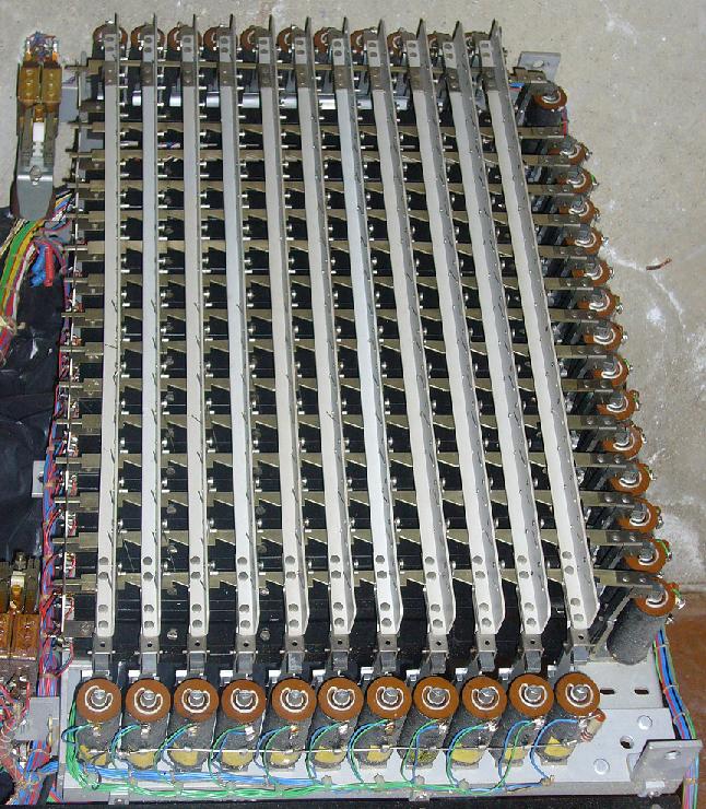
No wood, felt or other traditional materials beloved of the organ builder are used in this assembly, which is more suggestive of the hand of a professional engineer working in a machine shop. This impression is confirmed when one looks at a photograph of an actual system (Figure 9), which also depicts the steering and gating relays.
Figure 9. Hill, Norman & Beard's capture system (15 stops on 11 pistons) (© photo courtesy of John Norman)
This unit controls up to 15 stops and 11 pistons. The assembly is mounted on a steel baseplate, and many of the piece parts are fabricated from pressed steel and other metals. It is extremely compact, but it was possibly easier to maintain than was Compton's system as the contact wires appear to be more accessible.
One wonders whether a telephone engineering firm might have had a hand in designing this variant of Compton's system. At first sight it possesses superficial similarities to the crossbar switch formerly used in Western Electric and some other electromechanical telephone exchanges, but although some of the constructional features might be common there is little functional overlap between a capture system memory and a crossbar switch. Apart from anything else, a crossbar switch is volatile - it loses its memory as soon as the caller hangs up and cuts off power to the magnets. Nevertheless, a firm accustomed to making electromechanical communications equipment would probably have had little difficulty tooling up for the HN&B capture system. The work was in fact contracted out to a small firm in Hornsey, north London.
W A Wolsey oversaw the electrical architecture of at least some HN&B organs in the mid-twentieth century, and it was he who designed their contemporaneous capture system also. The HN&B system was the end of a line in that it represented the ultimate evolution of a series of capture systems that had appeared since the 1930's. Together with some others, it continued to be used until the 1970's when fully electronic capture mechanisms began to appear. These had to await the availability of computer-type memories which then finally swept away these remnants of the electromechanical era.
A number of electromechanical capture systems were introduced by various organ builders in the 1930's. They were fully electric analogues of the electropneumatic systems which had preceded them by some 20 years, and they were seized on partly because they were well suited to installation in all-electric detached consoles in which no wind was available. The main reason for their delayed appearance was because they were power-hungry on account of the number of large electromagnets they required, and it was not until the 1930's that the provision of sufficient DC power at low voltages became less of a problem for organ builders owing to the ascendancy of the UK National Grid during that decade.
This article has surveyed three representative systems - those of Willis III, Compton and Hill, Norman & Beard. Willis's was one of the earliest, with a design clearly based on the simple manual setter board - an automatic memory and switching element replaced each manual switch in a setter board of the same size. Although the system was conceptually simple, the requirement for a very large number of magnetically-operated memories made it cumbersome and probably rather expensive. Compton developed a system which required far fewer magnets, though at the expense of greater mechanical complexity. His system was also based on the orthogonal arrangement of a setter board with its rows and columns, but it addressed each switching intersection indirectly via its co-ordinates in the matrix. HN&B adopted a similar though thoroughly re-engineered system some years later.
These and similar systems held the field until the 1970's, when they were displaced by fully electronic ones. Although they showed evidence of considerable design and manufacturing skill, they all suffered from a major shortcoming - they only captured one setting at a time. In other words they only had a single memory level. To provide any more using electromechanical methods would have been unthinkable. The introduction of electronic memories did away with this problem at a stroke. However the old systems were eminently maintainable and repairable, and that in Compton's organ of 1937 at Southampton's Guildhall has recently been refurbished after nearly 75 years' service. No electronic system can possibly compete with this, dominated as they are by limited life partly due to rapid obsolescence.
This article was written so that details of these old and fascinating systems are documented before the limited information now available slips away for ever.
Grateful thanks are due to HWS Associates and particularly to Lucien Nunes for information on the refurbishment of the Compton organ in the Guildhall, Southampton. In addition, it was a great pleasure to receive much detailed information from Colin Mitchell concerning the key players who contributed to the design and manufacture of the Compton system. I am also indebted to John Norman for much information relating to the Hill, Norman and Beard system. Finally, thanks to Kimber-Allen UK Ltd for permission to reproduce material from their catalogue.
1. Willis' 'Infinite Speed and Gradation' Swell Control System, an article on this website, C E Pykett, 2011
2. "The Organ", W L Sumner, p. 324, Macdonald, London 1962
3. British patent 436737 dated 17 October 1935.
|