


|
|
|
Swell Control in Electronic Organs
by Colin Pykett
Posted: August 2006 Last revised: 24 December 2009 Copyright © C E Pykett
Contents (click on the headings below to access the desired section)
Electronic Simulations of Swell Boxes
Swell boxes in pipe organs vary widely in their effectiveness but the best are seldom simulated properly in electronic organs. When a real swell box moves from an open to a closed state, the volume of sound is not merely attenuated as it is when you manipulate the volume control on your hi-fi system. The tone quality generally varies as well in that high frequencies are attenuated more rapidly than the lower ones. This effect is infrequently simulated, but even when it is it can still be identified as artificial if the tonal characteristics are incorrect. Many electronic organs also attenuate the sound far too much when the "box is closed", nor do they incorporate means to prevent the sound varying too quickly. In a pipe organ it is impossible to close or open a swell box arbitrarily quickly if the linkage is mechanical, simply because of the inertia of the heavy mechanism. If the linkage is electric, the shutters (shades) will still respond with their own time constant regardless of how quickly the pedal itself might be operated. Getting all these factors right in an electronic organ is difficult, and its pedigree as a mere simulation is often revealed when they are wrong.
This article discusses the problem in detail, including circuits and techniques suitable for analogue and digital electronic organs developed over some twenty years. Much of it will be comprehensible by the general reader, but the more detailed aspects assume some technical knowledge in electronics. The desirable aspects of real swell boxes are first discussed before showing how to simulate them electronically.
This is not the place for a detailed dissertation on every conceivable aspect of pipe organ swell boxes. What concerns us here is how effective they are in an acoustic and musical sense, and how that effectiveness can be characterised objectively in ways which will enable a satisfactory electronic imitation to be constructed. Organists have a general understanding and appreciation of whether a swell box is "good" or not, and although individual opinions will vary, there is probably consensus on the main issues. Thus a box which attenuates the sound too much or too little will be judged unsatisfactory, and one which gives that subtle impression of suppressed power when enclosing full swell will be preferred to one which merely causes the sound to advance and retreat in an anodyne manner. Organists seem generally not to mind that the sensitivity of swell pedals is often greatest near to the point of closure, in the sense that a given amount of movement at this point will affect the volume of sound more than the same amount of movement when the box is nearly open. Indeed, many like and expect this behaviour. However they do not like it to be overdone to the point where it becomes impossible to exercise proper control.
Another important matter when imitating swell boxes is that the sound must not change too quickly no matter how fast the pedal itself is moved. This does not happen with a real box because it cannot. With a mechanical connection between the swell pedal and the shutters, the inertia of the heavy mechanism sets a limit to how quickly the shutters can be made to move. This is also true if the connection is electro-pneumatic, because then there is a minimum response time imposed by the mechanism regardless of how fast the pedal itself might be moved. This mechanical limit to the speed at which real swell shutters can move is an important factor to include in an electronic simulation of a swell box. The only circumstance in which the shutters will move exceptionally rapidly is when the old-fashioned unbalanced trigger type of swell is encountered. With these, the shutters will move extremely quickly under their own weight if you inadvertently allow your foot to slip off the pedal, to the accompaniment of a loud crash. I shall not be discussing the design of an electronic imitation of this sort of swell box.
It is probably fair to say that real swell boxes are most effective when constructed of wood rather than building materials such as bricks or blocks. Although the latter can demonstrate an impressive degree of volume control, their disadvantages are two-fold. Firstly, the volume control effect is exactly that - mere volume control. Subjectively it is no different to what you get when you twiddle the volume control knob of your hi-fi system. All frequencies from the highest to the lowest are attenuated in more or less the same way, and the sound just seems to ebb and flow without character. It is next to impossible to get that sought-after impression of pent-up power and thunder when using the manual flue doubles, reeds and mixtures with such a swell box. The second problem is that boxes of this type usually have a dynamic range that is simply too great, and this compounds the difficulties just outlined. If particularly quiet stops such as a salicional, dulciana or the celestes are enclosed in this type of box, they can vanish to the point of inaudibility when it is closed.
A wooden box, on the other hand, allows acoustic leakage to occur in various subtle and desirable ways. Because the wood panels can vibrate, they can lend colour to the sound at various frequencies as the shutters open and close. Their vibration also means that sound will leak out even when the box is fully closed. Moreover, because more acoustic power is generated by the pipes at the lower frequencies, it is in the lower frequency region where sympathetic vibration will be preferentially set up. The size and mass of the panels also makes them more efficient resonators at the lower frequencies. Taken together, these reasons explain why a wood swell box is more likely to possess the desirable characteristics outlined above. When it is closed it acts as a low pass filter, an extreme form of treble-cut tone control, allowing sound to leak out progressively more effectively the lower the frequency. Indeed, at the lowest frequencies a swell box is called upon to handle - about 30 Hz, corresponding to the bottom note of a 16 foot stop - there may be little or no attenuation of sound level at all when the box is fully closed. However there will always be some attenuation of the upper harmonics of pipes having these low pitches.
Electronic Simulations of Swell Boxes
I have spent a lot of time investigating the characteristics of swell boxes quantitatively and objectively, but I will not attempt to reproduce the results here in detail. Apart from the intrinsically boring nature of the material, every swell box is different to every other, so the question is immediately begged as to which one should be simulated. Therefore I make no apology for reducing a complex and confusing mass of data to a single, simple electronic model. To my ears it encapsulates all of the major characteristics of real swell boxes which are worth simulating, and these are recapitulated below:
Only when these features are incorporated in an electronic organ will the simulation of its swell boxes be acceptable. When they are not, and they generally are not, one gets the usual tiresome result that the sound can almost vanish, virtually instantaneously, or it can reappear again in a similar manner as if by magic. Full swell with "box closed" sounds anaemic and thin. It is a fact that even when the simulation of the tones themselves are good in a digital organ, the overall effect of the instrument can be virtually destroyed by an inartistically designed swell system.
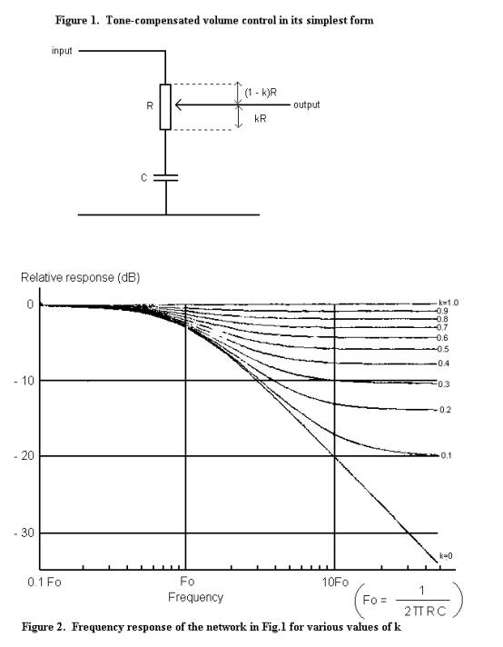
Beginning with an analogue circuit of the simplest form, that in Figure 1 incorporates all but one of the necessary features. I first looked at it as a candidate for an electronic swell pedal over 20 years ago, and have used it (and its digital equivalents) many times since. All the electronic organs whose sounds are included on this website in effect use this technique, though its actual embodiment is considerably more complicated as will be shown presently.
Without the capacitor C, the circuit reduces merely to a volume control of the type used in any sound system. R is the standard variable resistor (potentiometer) used in these systems, which taps off a proportion of the input voltage dependent on the position of the sliding contact. In an electronic organ the swell pedal would often be mechanically coupled to this component in this simple arrangement. But by including the capacitor its performance is transformed. Firstly the potentiometer no longer attenuates the input to zero, as it would without the capacitor. Secondly there is a progressive treble-cut effect as the volume reduces. Thirdly the rate of treble cut increases towards the "box closed" position provided the potentiometer is linear (i.e. has a linear variation of resistance versus slider position). Therefore this simple circuit satisfies the first three criteria listed above. The fourth one, that of limiting the maximum rate at which the sound can change, will be discussed later.
Certain issues of good engineering are assumed in Figure 1. The output impedance of the source which feeds the potentiometer must be much less than the value of R, and conversely the input impedance of the circuit which receives the output from the slider must be much greater than R.
Although the circuit is simple the mathematical form of its transfer function is decidedly not, and it is an algebraic expression not worth reproducing here in view of its complexity. However I have plotted it graphically in Figure 2 in terms of two variables - audio frequency along the horizontal axis, and the position of the slider which is equivalent to the position of the swell pedal. The latter is expressed in terms of a variable k which is unity for "box fully open" and zero for "box fully closed". Looking first at the "box open" case (k = 1) we see that the circuit has no effect on the incoming audio signal because the graph is flat with frequency. By contrast, at "box closed" (k = 0) there is a pronounced treble cut effect. Only the lowest frequencies emerge unchanged, below a frequency equal to 1/2πRC at which the circuit attenuates the input by 3 dB, about 30% (in the expression just given, R in ohms and C in farads gives frequency in Hz). This frequency, Fo in the diagram, is conventionally called the corner frequency of a filter circuit. Intermediate positions of the swell pedal, denoted by intermediate values of k, result in intermediate mixtures of these two extreme characteristics as the family of curves shows.
One further feature of the circuit is important, and that concerns the vertical spacing between the extreme right hand ends of the curves. It can be seen that the spacing for values of k near to unity is small, whereas for values near to zero it is much larger. This endows the circuit with the desired sensitivity near to the "box closed" position.
This
simple control has precisely the subjective aural feel and behaviour of a typical
pipe organ swell box,
and if this were all there was to concern us then this article could end
here. Some practical considerations now intrude, however. An
additional bonus conferred by voltage control solves the remaining design
problem, criterion 4 above, which is the need to imitate the inertia of heavy
swell shutters. Voltage control can solve this problem if a suitable
electronic time-constant is incorporated, and this also reduces still further
any residual problems due to noise when operating the potentiometer..
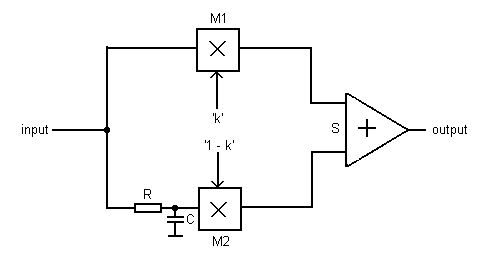
Figure 3. Voltage-controlled equivalent circuit
An exact equivalent of the circuit of Figure 1 using two analogue multipliers (or voltage controlled amplifiers) M1 and M2 is shown in Figure 3. One of the multipliers represents the portion of the potentiometer lying above the slider, and the other represents the portion lying below. The outputs of the two multipliers are summed by the amplifier S. The gain of each multiplier is controlled by a separate voltage, proportional to k and 1-k respectively, but as we shall not be using exactly this circuit, the method of deriving these control voltages will likewise not be described. Note that the tone control components are now in the form of the two discrete components R and C which are fixed in value.
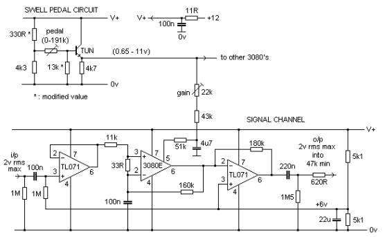
A simplified version of this circuit was developed by my late friend and electronic organ collaborator Dr David Ryder, and a variant of his design is shown in Figure 4.
Figure 4. Complete circuit of the swell control
The complete circuit consists of two sections - the swell pedal circuit which generates a control voltage depending on the current position of the pedal, and the signal channel(s) which it controls. As many signal channels as desired can be controlled simultaneously from the one swell pedal circuit and the outputs fed to separate loudspeakers.
Signal channel Each signal channel uses a CA3080E operational transconductance amplifier (OTA) as the variable gain element, as in Figure 4. Its operation is virtually identical to the configuration of Figure 3 but the actual circuit is rather simpler, needing only one multiplier instead of two. It has been designed to handle signal levels up to 2V rms (about 6V peak-to-peak) because this is the maximum standard output from most digital sound systems today (the same as computer sound cards, CD and Minidisc players).
The corner frequency of the circuit is about 145 Hz, meaning that frequencies below this are not subjected to significant attenuation when the swell is "fully closed". The corner frequency is defined by the 11k resistor and the 100nF capacitor at the input to the CA3080. This frequency corresponds roughly to the fundamental of an 8 foot organ pipe sounding tenor D (the D below middle C), but it is important to observe this does not mean that this note and those below it are not controlled by this circuit. Because the harmonics of this note still lie well above this frequency, its subjective volume will still be affected as the swell pedal is operated. But the point is that its tone quality will change, as it would if was an actual pipe in a real swell box. Even bottom C on a quiet flue stop such as a Dulciana will experience some effect with this circuit because of the presence of harmonics extending into the controlled frequency region. However, because the fundamental frequencies themselves of these very low notes are little affected, this is why the circuit imitates the desirable pent-up thunderous effect of a real wooden swell box when it is fully closed.
Unfortunately the CA3080 is now obsolescent, but a possible replacement still exists in the LM13700. The transconductance figure of both types is the same, therefore it should be electrically equivalent. However it is a dual package containing two amplifiers, so it is not a plug-in replacement. An alternative approach is to use an OTA built from a few discrete components, and in these days when many useful analogue integrated circuits are now disappearing from the catalogues this is becoming increasingly necessary. For the highest quality audio work this can be an advantage however, as discrete circuits will generally out-perform their integrated counterparts in terms of noise, distortion, etc if properly designed.
Swell pedal
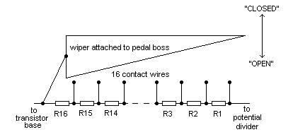
circuit The swell pedal itself operates a 191k variable resistor. This is an unusual value because I prefer to use a standard electric action pipe organ swell pedal in these applications operating a chain of fixed resistors. I usually use a Kimber Allen SP16 16-contact unit, fitted with gold rather than the usual silver contact wires to special order. These are connected to a resistor chain arranged so that the pedal is effectively a linear potentiometer, feeding a varying control voltage from 0.65 to 11 volts as a linear function of pedal position into any number of signal channels. This form of variable resistor is far more reliable and trouble free over periods of many years than would be the case with an ordinary rotary potentiometer, but if it is preferred to use one of these then it should be linear and arranged so that the resistance variation from "open" to "closed" is about 191k.
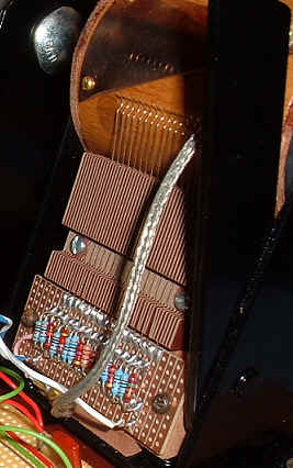
Figure 5. Resistor chain attached to K-A 16-contact swell pedal The configuration of the fixed resistors making up the chain and the way they are connected to the contact wires of the swell pedal is shown in Figure 5. “Box open” corresponds to the situation where the pedal wiper shorts out all the contact wires. “Box closed” is when the wiper is not in contact with any of the wires. The wiper itself is connected into the circuit as shown. A photo of an actual resistor chain wired to a K-A swell pedal is at Figure 6. The resistor values are in the following table:
The resistor chain in Figure 4 is fed by a fixed potential divider giving 11 volts, and it is terminated at the base of the transistor. “TUN” in the diagram means “typical universal NPN transistor” such as the BC109, BC183 or almost any other general purpose silicon small signal device. The transistor operates as an emitter follower whose output impedance is about 150 ohms. This is well able to drive the VCA’s in as many signal channels as necessary. Ignore
the remarks about “modified values” in Figure 4, which were merely an aide
memoire for my benefit. Trimming The gain of each signal channel is adjusted to unity using the 22k preset in Figure 4 with “swell open”.
Time constant The time constant of the system is about an eighth of a second (125 msec), defined by the 4.7uF capacitor and the resistors in the network feeding pin 5 of the CA3080. Therefore if the swell pedal is operated rapidly, you will hear the sound grow or decay slightly more leisurely as it would in a pipe organ with, say, an electro-pneumatic swell shutter mechanism. The time constant also smooths out the jumps in sound level which would otherwise be noticeable with a 16-contact swell pedal. The effect is highly realistic, and the system gives a completely smooth and noise free means of achieving expression control. Parasitic oscillation The TL071 operational amplifier from which the output is obtained is an excellent device in most respects, but it is prone to HF parasitic oscillation at high amplitude if capacitively loaded. This can happen with a length of screened cable connected to the output. To prevent this, it is most important to include the 620 ohm snubbing resistor in series with the output as shown in Figure 4. This prevents conditions arising which could otherwise encourage oscillation. Some power amplifiers can be ruined if high amplitude/high frequency parasitics are inadvertently applied to their inputs, because they themselves can then go into a latched-up parasitic mode from which they cannot recover. The symptoms are a loud hum for a few seconds, followed by a smell of burning, smoke, then silence! Don’t laugh, I’ve experienced it. Just think how lucky you are for me to be telling you this.
Figure 6. Resistor chain wired to the 16 K-A swell pedal contacts
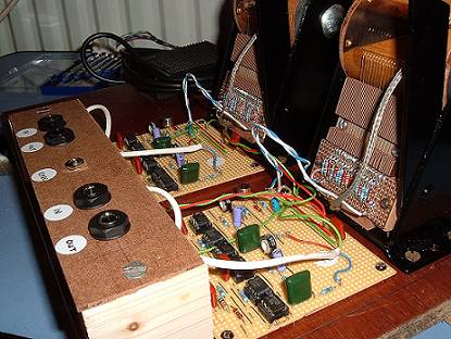
The chain of 16 resistors attached to the contacts of the swell pedal is shown in Figure 6, and the prototype of a complete dual swell pedal assembly is at Figure 7. Each of the two swell pedals in this assembly controlled two analogue signal channels emerging from a digital organ (i.e. four sound channels in all).
Figure 7. Prototype dual swell pedal assembly controlling 4 signal channels (2 per pedal)
The analogue technique described above gives an entirely satisfactory imitation of a real swell box. It can be applied to the analogue output signals produced by a digital organ before they are sent to the power amplifiers, and it is more realistic in many cases than the inbuilt digital form of swell control in these instruments. However there are various ways to implement digital control directly as well.
The most direct method, though not necessarily the most efficient in computational terms, is to implement the circuit sketched in Figure 3 using a digital signal processing (DSP) software algorithm in the appropriate signal paths. The two multipliers and the summing amplifier at the output are trivial to implement, and the RC network is a straightforward first order finite impulse response (FIR) digital filter. The inertial time lag applied to the two control inputs k and 1-k can also be realised using a first order FIR filter operating on the input from the swell pedal. However, all this presupposes that you have access to the source code of the computer programs used by the digital organ and are able to modify it. Unless you are in the digital organ manufacturing business, or unless you have written your own software synth, this situation will be relatively rare.
It is more likely that you only have keyboards which supply MIDI codes to some form of digital sound processing engine, and in this case the simplest form of swell control is that which uses MIDI Continuous Controller 7. Any commercial MIDI keyboard will send a volume message in this format if the Volume wheel is operated. Therefore, the volume of the stops corresponding to this keyboard will respond appropriately. It should not be too difficult to arrange for the potentiometer normally operated by the Volume wheel to be operated instead by a swell pedal if desired. However, the problem in this case (assuming that the sound engine responds to CC 7 in the first place) is that you will only be able to control volume - no tone control effect will be possible. Therefore none of the desirable advantages of the analogue system described above will be available.
It is impossible to go much further here because of the variety of sound engines available, but one technique will be outlined for those which use SoundFonts. It is possible to make changes to the default settings in SoundFonts which offer more flexibility than merely affecting the volume of stops via MIDI CC 7. A SoundFont editor such as Vienna will be necessary to implement the following suggestions. Firstly it is worth mentioning that it is possible to arrange for certain stops in a department to remain unaffected by a swell pedal, even though the rest of the stops will. This can be useful on a department with a loud solo reed such as a Tuba, which on most pipe organs would not be enclosed in a swell box. To do this, the following changes need to be made to all Instrument Zones of the stop(s) in question:
Zones so modified will then not respond to the swell pedal. Secondly it is possible to arrange for the tone quality of zones to be varied in response to CC 7, rather than their volume. This is the same effect as that introduced by the analogue technique described earlier, which is in effect a tone control rather than a volume control. This can be simulated in a SoundFont by causing the swell pedal to change parameters other than the attenuation. One way this can be done is as follows:
Operating the swell pedal for that Instrument (i.e. stop) will then change the cutoff frequency of the low pass filter which a SoundFont implementation assumes to be present, rather than the signal attenuation. The initial filter cutoff frequency for each zone will also need to be chosen appropriately in the bottom left hand pane of the Vienna editing screen, and some experiment will be necessary here to get the best effect.
|