


|
|
|
The Evolution of Electric Actions by Colin Pykett " in practice they [electric actions] satisfy only those builders whose tonal ideals, like their instruments, are virtually outside the realm of true organs" Peter Williams & Barbara Owen, The Organ, Macmillan, London 1988 Posted: April 2005 Last revision: 6 July 2020 Copyright © C E Pykett
Abstract The story of electric actions for pipe organs during the twentieth century is not one of unalloyed progress. Some still regard an electric action as one of the most unreliable types, and it is not uncommon to find players who insist on the presence of an organ builder when they are to give a recital on an electric instrument. This article examines how electric actions have evolved, and shows that there seemed to be a lofty disregard for the principles of good electrical engineering by some organ builders during the twentieth century. It then goes on to examine whether this resulted in real or perceived unreliability, and whether the situation changed when electronic (as opposed to electromechanical) control systems started to appear around 1960. It also shows that some electrical equipment, marketed in the 1970's and possibly still in use, was potentially lethal.
Contents (click on the titles below to access the desired section)
The quotation at the head of this article is by two of the world's leading authorities on the organ. Is it fair? It is a subjective judgement which certainly could not be considered fair and reasonable if there is no basis in fact to support it, and in this circumstance it could be dismissed as one of those unscholarly generalisations which are regrettably all too common in the organ world. This article investigates why electric actions are sometimes regarded in this light by looking at them in a more objective way, and it will then be for readers to make up their own minds on the matter.
Pipe organs with an electric action have always been associated with unreliability in the minds of many players, and even today it is not unknown for a recitalist to insist on the presence of an organ builder when performing on one of these instruments. Is this association simply a myth with no foundation in fact, perhaps encouraged by the mystery attached to anything electrical? Or is it rather more than just a figment of the imagination? This article explores the major issues and concludes that there are indeed grounds for the belief, grounds which still exist today with some recently built organs. Few of the problems to be explored exist, indeed they could not exist, with mechanical actions.
The
idea of operating the pallets of an organ electrically arose in the 1820’s
when the electromagnet was invented, and it gained momentum towards 1850 as the
electric telegraph developed. This
was because the two systems, each consisting of a contact operating a remote
electromagnet, were similar in some engineering aspects and therefore they
developed in parallel. However the
earliest organ actions were unreliable largely because of the inability of
contemporary batteries to provide relatively high currents at infrequent
intervals, the reverse of the telegraph situation which used lower currents but
on a semi-continuous basis. Also
telegraphs were maintained daily by skilled technicians, and there was no
shortage of money to ensure the batteries were kept in peak condition.
This was the reverse of the organ situation.
It was not until the 1890’s that the magnitude of the battery problem
began to be reduced by builders such as Walker, Hill and Hope-Jones.
They used rechargeable accumulators instead of primary cells when other
sources of power were unavailable, despite blatantly untruthful claims by
Hope-Jones to the contrary [1, 2], but otherwise they preferred low voltage
dynamos driven from the blowing gear. Although
accumulators when in tip-top condition were more or less adequate for the job
they required careful maintenance, recharging and periodic replacement, and
without this they would fail without warning.
Anyone who has experienced a car that will not start will know that this
problem still persists more than a century later. Yet
even in situations where ample power was available, which in practice meant the
ubiquitous dynamo used exclusively up to about 1950, unreliability continued.
Sometimes this was of a type similar to that experienced with pneumatic
actions, such as notes or stops failing at random.
Or a player could jab repeatedly at a combination piston only to find it
would work intermittently at best. At
other times the problems were of a type peculiar to electric actions, such as
the entire instrument collapsing without warning. A surprised audience
experienced a débacle of this nature when a performance of
Ligeti's Volumina at the Royal Festival Hall in London was more than
somewhat affected by
the complete failure of the organ [17]. Many players with experience of mid-twentieth century actions will be
able to reminisce at length about such matters.
After about 1950 low voltage transformer-rectifier sets connected
directly to the mains began to displace dynamos as the prime power source,
slowly at first but gathering pace as costs came down and reliability increased.
(Early “metal” rectifiers had an unfortunate tendency to fail with a
hideous odour of rotten eggs. Fortunately
this problem disappeared when high-current silicon rectifier diodes became
available. Smoothing capacitors,
although not always used, have been known to explode and shower the choristers
and the interior of the organ with what looked like snowflakes). The
second half of the twentieth century also saw the progressive introduction of
purely electronic solid state control systems.
Although the manufacturers of these systems continue to insist that they
are more reliable than their electromechanical predecessors, the unpalatable
facts tell rather a different story. When
they fail, oh boy do they fail. During
a TV broadcast in 1999 [16], the unfortunate Wayne Marshall sat helpless at the
detached console of the then new Marcussen organ at the Bridgewater Hall in Manchester when the
electronic transmission system failed completely.
Around that time the famous organ at Notre Dame, Paris, had also been
rendered silent for a long period when the computer-based transmission failed.
In 2004 the expensively-restored organ at the Royal Albert Hall in London
failed, necessitating the use of an electronic substitute at a Promenade
concert. This story even made it into the national press [14].
Taking yet one more of many recent examples at random, the organ at the
important city-centre church of St Peter in Nottingham currently (August 2010)
languishes unplayable because of an unrepairable electronic transmission system
- and they propose to install a hybrid pipe/digital organ as a result [15]. Not
terribly impressive, is it? Other similar instruments have been affected by nearby radio
transmitters, mobile phones or even fluorescent light fittings in the building.
And the recently rebuilt organs of St Eustache in Paris and St Mary’s
cathedral in Edinburgh are but two high profile instruments which have suffered
from lightning strikes owing to the fragility of electronic circuits.
After I had pointed out some of these problems in a widely read journal [3] a
well known organ adviser, who had played a leading role in at least one of the
stories mentioned, rather foolishly wrote complaining that I had
“damaged the business” of a certain supplier of electronic organ
transmissions - in which he presumably had an interest.
While it would have been fascinating to observe how this allegation might
have been tested, it did demonstrate how sensitive is the trade even to
objective discussions of the limitations of their products, and such experiences
only
increase one’s determination to get to the roots of the matter. In a
situation such as this it is reasonable to suppose that the tip-of-the-iceberg
syndrome applies as it does for other statistics – for every unfortunate
occurrence that makes it into the public domain, there must be several or many
others which do not. Following the
publication of the article referred to, another well known figure agreed with my
cautionary remarks about electronics in organ actions [4].
He repeated my comments about the limited life span of electronics,
a point made still more recently by another organ builder who also maintained
(correctly) that anything electronic has an intrinsic and inbuilt obsolescence
quite inimical to the dignified longevity of the traditional pipe organ [5].
The latter article also suggested that electromagnets themselves have a
shorter life than pneumatic motors, thus returning to the reliability theme. On
the basis of the foregoing it is difficult to refute the statement that electric
actions continue to be unreliable and unpredictable to an extent which still
causes their shortcomings to be discussed openly, at least by those with open
minds. Those who deny this can only
have their heads in the sand, or not be possessed of sufficient knowledge, or
perhaps have vested interests in other directions.
In this article we shall now explore why this situation has persisted so
long, and thus whether the dismissive view of Williams and Owen quoted above has
an objective basis in the science and engineering of electric actions. Except for some of the most recent, electric actions are full of metal-to-metal contacts in their hundreds. For much of the 20th century, organ builders’ rules for their fabrication seemed to be along the lines of: “Use any old metals you like. Don’t bother about corrosion or protecting them from the environment, just rely on a wiping action and a bit of sparking to shift the dirt and stop corrosion building up. Don’t bother with details like the optimum contact pressure or the shapes of the contacting surfaces or the required contact area (what?). And just screw the whole lot onto a bit of wood”. This
approach, which will be amply demonstrated in what follows, shows that organ
builders as a rule seemed entirely unaware of the decades of development that
had already gone into the design of professional low voltage electrical
equipment by the end of the nineteenth century, or maybe they just didn’t
care. Such equipment included the
telegraph, the telephone and early Hollerith-type office machinery. Whatever the reason, nothing epitomises the cult of the
amateur more than some of the electrical items conjured up since by organ
builders. But to illustrate the
importance of getting apparently mundane details right, a good example is the
design of relays. Samuel Morse is often credited with the invention of the relay, but in fact it was more likely the brainchild of Joseph Henry. However it seems fair to credit Morse the practical man with adapting the idea successfully for use in his early telegraph systems, whereas the more academic Professor Henry appeared to regard it as little more than an entertaining curiosity. Among other applications, Morse developed a sensitive relay well before 1850 which could amplify the feeble currents sent down the long telegraph lines so vital to communications in the USA, and thus render them able to operate equipment such as ribbon printers to render the dots and dashes visible on paper tape. An important feature was the need for high reliability over extended periods, which meant that much attention had to be devoted to contact design among other matters. From these early beginnings, relays have been subjected to continuous improvements and this still continues today. Regular international conferences are held on the subject, and a substantial specialist literature is continually growing. At the time of writing (early 2005) a book is available describing the Matsushita range of relays and their design concepts [6]. This example was chosen randomly and there are many others. Those
unaware of this scenario, and one wonders whether the number could include some
organ builders, might raise their eyebrows at this point.
In today’s world which is dominated by digital microelectronics, why is
so much attention still devoted to an ancient electromechanical device such as a
relay? The answer lies, as it
always has, in the importance and size of the telecommunications industry.
From the start relays have played an essential role, firstly in telegraph
then in telephone systems. Until
they were largely displaced by electronics in the 1980’s they performed
virtually all the binary logic operations in the UK’s Strowger-switched
telephone exchanges, and a typical relay of the 1960’s was the well known Post
Office type 3000 unit. A study of the design of this sturdy and well proven item
would undoubtedly have improved the performance and reliability of many
mid-twentieth century organ actions. Indeed,
I have often wondered why organ builders did not actually use cheap yet
high-performance components such as these instead of making up their own
inferior and more expensive imitations out of bits of wood, felt and wire.
Yet even in this age of digital exchanges and routers, relays are still
used in their countless millions in communications systems worldwide, and the
tiny fully-encapsulated BT47 style of device made for British Telecom as of 2008
is a
typical and beautiful example of the cost effectiveness of the breed.
The fact it only costs 79 pence ex-VAT (again in 2008, and under 50 pence
in quantity) confirms the huge production quantities
still involved in the relay business. Like most modern relays, this type
is also virtually noiseless, an important attribute for use in organs.
This type of relay is illustrated in Figure 3 below.
In
the 21st century, what tainted logic still makes an organ builder pay
upwards of £30 for an electromechanical reverser unit from a supplier of organ
parts when he could hook up his own from a pair of industry standard relays, and
gain enhanced reliability at the same time?
Appendix 1 develops this theme and contains some representative circuits. There
are many factors involved in the design and fabrication of electrical contacts
and this article can only skim the surface of a vast subject comprising a
fascinating mixture of art, science, engineering and hard experience. Rather
like organ building itself, in fact. It
is appropriate to begin by reminding ourselves of the far from benign
environment in which the contacts must operate. The
atmosphere in churches is frequently damp, and because the air is often cold it
deposits some of its retained moisture on metal surfaces in the form of
condensation when the heating is turned on for services. This is because the air
heats up more quickly than anything else in the building, partly because of its
low thermal capacity and partly because it is the air which first comes into
contact with radiators etc. It is
well known (particularly by those of us who wear spectacles in cold weather)
that when moisture-laden air meets colder surfaces, some of the moisture
condenses onto them. Thus ferrous
metals prone to rusting and other forms of corrosion suffer rapidly under these
conditions. Such metals are widely
used for the magnetic components of organ actions.
The use of cadmium plating does little to prevent these effects over long
periods – in fact this has its own peculiarities including a tendency to
develop a white powdery coating in certain environments. Non-ferrous metals such as tin, which is sometimes used to
plate the surfaces of electrical contacts especially in connectors, can also
degenerate over time ("tin pest"). Many organ
builders will know that the effect is so severe that it can render ordinary
tinned copper wire virtually impossible to solder when patination of this type
has set in. It is extremely
difficult to remove. Because the air in churches is also frequently laden with impurities such as incense (benzoic acid), oils and other hydrocarbons resulting from the burning of candles and from heating systems, further damage is done to the contacts and connectors in the low voltage circuits of an organ action. Silver, a frequently used material, becomes completely blackened under such conditions with a tarnish which resists the most determined mechanical efforts to remove it. More will be said about this problem later because it illustrates some interesting and important electrical effects. If an organ is sited in a secular building, alternative or additional contaminants can include the exhaled products of myriad smokers, and those from theatrical effects such as the fogs and pyrotechnics used on stage. The brown nicotine-laden tar which forms in revolting drops and streaks on the walls and ceilings of such buildings also accumulates on the contacts in organ actions, although recent anti-smoking legislation should prevent this problem in the future. The
effects of this cauldron of airborne pollutants can be observed if the key
contacts are wiped with a tissue or cotton bud.
This will seldom be adequate to clean them effectively, but the results
once seen are usually sufficient to convince most people that exposed contacts
in an organ action are just not up to the job.
No wonder such actions are so prone to unreliability and failure.
Some form of well sealed enclosure is the least that is required to slow
down the onset of these major problems, yet how often are they used in organs? And I haven't even mentioned the problems caused by cobwebs and insects, both dead and alive ..... The
metals chosen for the contacts must satisfy both mechanical and electrical
engineering criteria. Thus they
must have sufficient springiness to separate when the associated circuit is
opened and to retain the desired separation over a period of several decades.
The contacting areas must be capable of conducting the required currents
whenever the circuit is closed, again over a considerable period without
requiring excessively frequent interventions for cleaning.
These obvious characteristics are not always easy to achieve in the
adverse environments encountered in organ building.
Solid gold, for example, is an excellent contact material for certain
circuits in an electrical sense for reasons which will be discussed later.
However it cannot take a temper, which implies that alternative means
have to be used to render gold contacts sufficiently springy.
This mutual exclusiveness is characteristic of the problems encountered
in contact design. Historically,
organ builders seem to have selected a material mainly on the basis of its
mechanical characteristics, and then they went on to assume that because it was
metallic its electrical characteristics would automatically be satisfactory.
Nothing illustrates this approach better than the widespread use of
phosphor bronze. Phosphor bronze is
an alloy of copper and tin with about 0.5% of phosphorus, and it will readily
return to its original position after being subjected repeatedly to a moderate
bending strain. It can be formed or drawn easily into a variety of shapes, it
has a high melting point, and for all these reasons it has been widely used for
contact fabrication across the electrical industry for many years.
However it is generally unsuitable for use as a contact material directly
because it is highly reactive with the constituents of the atmosphere.
Thus professionally designed contacts in relays etc employing phosphor
bronze springs use other metals or alloys to close and open the actual
electrical circuits. Organ
builders, however, have frequently not bothered to do this and have relied on a
modicum of sparking to keep the contacts clean.
This crudeness of design and realisation was confirmed by an article
which showed how fond organ builders are of sparks to keep silver contacts clean
also [7]. Silver
is in many ways a curious choice for contacts.
It has the highest electrical conductivity of all the common metals, just
beating copper and exceeding that for gold by a considerable margin. I can only assume that this largely irrelevant factor has
been responsible for the widespread use of silver contacts for over a century,
because the disadvantages of the material are several and considerable.
Firstly it is a matter of everyday observation that it is highly reactive
and tarnishes rapidly. The black
patination which builds up, particularly if gas heating or cooking is in use, is
stubborn and difficult to remove mechanically.
Therefore contacts with a wiping action will turn just as black as those
without. Secondly, silver does not
“remain fairly conductive” as maintained in the article just referred to [7]. In fact the matter is far more
complex and of considerable importance. Most
professional engineers will know that silver must not be used for switching
voltages below about 6 volts because when patinated it has an extremely high
resistance in this circumstance. Above this figure the resistance drops sharply and becomes
less of a problem. A full
understanding of the reason for this behaviour would require a digression into
quantum theory and the so-called tunnel effect which, though fascinating, would
scarcely be justified. The main
point to bear in mind is that silver will be more reliable for old fashioned
electric organ actions working on 12 volts or so, sparks or no sparks, than
for more modern electronic keying systems (including so-called diode keying
which is discussed later) if the system works at the common “logic” level of
5 volts. To
emphasise this with an anecdote, I was once called to an instrument whose key
action worked reasonably well but whose piston action was horribly unreliable.
Both the key and piston systems were electronically controlled.
The organ had elderly but high quality Herrburger Brooks keyboards which
had been recovered from a Compton instrument of the 1950’s; the labels inside
the key cheeks proved that. They
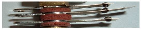
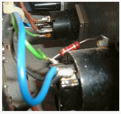
were still fitted with the original contact assemblies of that maker (see Figure
5), and at first I was at a loss to understand why the organ was plagued by
phenomenon mentioned. All of the
silver wires, wipers etc were of course completely blackened, but this did not
explain why the key action worked reasonably whereas the pistons did not.
However all became clear when I applied a voltmeter to the common rails
of the two systems – the key action was working at 15 volts whereas the piston
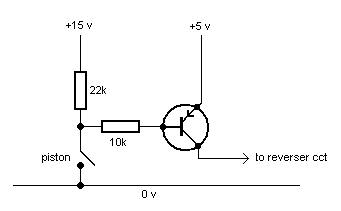
action was at 5 volts, and silver will not work reliably at 5 volts.
The problem was solved by interposing a simple transistor level-shifter
between each piston contact and its associated electronics; this circuit applied
15 volts to the piston contacts but only presented 5 volts to the electronics of
the combination system when a piston was pressed.
This was a much cheaper solution to the problem than the proposed
alternative of jettisoning the entire keyset, and it enabled the beautiful and
irreplaceable ivory and ebony keys and the comfortable playing experience to
remain undisturbed. The level-shifting circuit is shown in Figure A3 (Appendix
1). Gold is the material of choice where low voltages and currents have to be switched, as in electronic (solid state) keying and transmission systems, because it is virtually unreactive and the surfaces will therefore remain clean and shiny for an indefinite period provided they are protected from the worst effects of the environment. Its unreactiveness is why the strongest acids have to be used to assay gold for purity. But the solid material frequently cannot be used for reasons besides cost because it will not take a temper – there is no way that gold can be made springy. This is why the clasps and catches on gold jewellery fail so frequently. Thus so-called gold contact wire is usually made from a core of material such as phosphor bronze onto which a thin covering of gold is rolled, not plated. This results in an electrically fragile material however, as the slightest trace of sparking will penetrate the gold surface and render the contact useless. It can only be used for electronic switching in which the currents are minute, no more than a few milliamps. Nor must there be any current surge at the instant the switch closes, perhaps due to excessive input capacitance in the controlled circuit, as this also will be sufficient to destroy the contact over time.
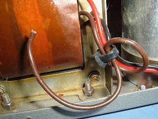
A number of mechanical as well as electrical matters have been rehearsed above. However there is a further mechanical factor which is particularly important in contact design: the need to reduce the onset of fatigue failures in structures such as contact wires which are subjected to continuous bending strains.
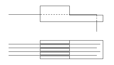
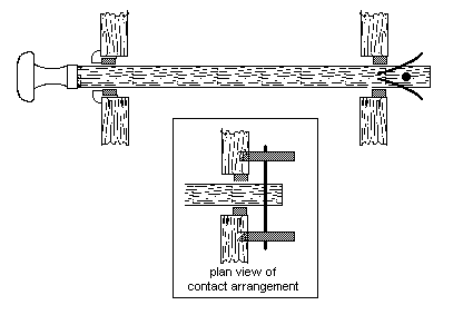
During the first half of the 20th century the contact block used in keyboards evolved into the form familiar today, though it was commonly constructed of wood until about the 1940’s as shown in Figure 1. An important function of any contact block is to relieve the brittle soldered connections from strain caused by the wire movement, otherwise frequent and early failure would result due to fatigue (a problem which besets some of the cheaper electronic organs to this day). Another function is to maintain the separation between the contact wires.
Figure 1. Typical wood contact block (c.1930) The contact wires were usually of phosphor bronze or sometimes silver, sprung so their rest position was at the base of the grooves. Sometimes the open ends of the grooves were covered with a slip of thin wood or brown paper. Multiple wires were necessary before circuit techniques were developed requiring only a single contact per key (see later for a discussion on the evolution of circuits). Although this design decoupled the soldered joints from movement, the sharp bend at the point where the wire emerged from the base of the block was undesirable in itself. Moreover it invited failure at that point as the wires flexed continually. Thus subsequent designs reduced this problem. Compton used their own design of contact block, functionally similar to that just described but with a means of motion decoupling which anchored the wires without requiring them to be bent through sharp angles. Unfortunately the block was manufactured as a thermoplastic moulding which was soft and rather fragile and thus easily damaged, both mechanically and by heat from a soldering iron. Various supply houses also offer their own designs. The Good, the Bad and the Ugly
It is appropriate at this juncture to look at some further examples of electrical contact practice. The first is a changeover contact set taken from a pipe organ relay; it was purchased from a supply house in the late 1980’s and therefore represents modern practice by organ standards. To forestall argument on this point, the item could still be obtained when this article was posted in 2005.
Figure 2. A recent example of poor practice
Figure 2 shows the contacts in question. They are depicted in as-new condition because the relay has never been used for reasons which will become obvious. The misshapen contact springs are of nickel plated phosphor bronze, with silver contact studs. Note how the contacts are misaligned, and that the “set” of the normally-closed pair is quite wrong (they do not close at all). Note also that the assembly is held together with only one bolt, allowing the contacts and other components to rotate laterally if it loosens. The whole thing is open to the atmosphere with no attempt at enclosure. This appalling example of current organ engineering was incorporated in a relay which costs nearly £30 today. Two other examples, representing good engineering practice this time, are shown in Figure 3. The top picture is a similar close-up of a changeover contact (one of four) in a relay of a type still used widely in the electronics industry, purchased some 30 years ago and used constantly since. The fact there is no solder on the tags might belie this, but the relay is used in a plug-in holder which facilitates replacement or servicing should it be required, another advantage of using industry standard parts rather than those made specifically for organs. It costs around three US dollars, and far less in quantity. The contacts are of gold on phosphor bronze spring arms, rated at several ampères (amps for short) and they are enclosed in a transparent plastic enclosure. Note the as-new condition of the contacts, almost as though they were made yesterday. Even the unplated phosphor bronze still gleams 30 years on, and this is undoubtedly because of the enclosure. Although the cover is not gas tight (it can be readily removed), this is a good demonstration of the benefit of enclosing electrical contacts. The lower photograph is of a much smaller item not much larger than one's thumb nail. This is the totally sealed BT47 telecoms-type relay referred to earlier, shown both as supplied and with its top sawn off. A suitable socket is also shown into which the relay can be plugged if it is not desired to solder it directly into a circuit board. This relay costs typically one US dollar in medium quantities and the socket a few cents. It has two changeover contacts, but because of the small size of the device they are rated at one amp. However this is ample for operating the magnets (which must be diode-suppressed) in stop key units or drawstop solenoids which typically draw only half this figure, therefore two of these items could be used for the electromechanical reverser unit described in Appendix 1.
Figure 3. Recent examples of good practice (upper: 5 amp changeover contacts; lower: BT47 type relay) Which
relay would you prefer to use? Correct! So why is the organ-specific one still available and widely
employed? I have no idea – there
can be no sensible answer, though I am sure there will be those who will rush to
tell me otherwise. A reason sometimes quoted is that commercial relays are
too noisy for use in an organ, though this is simply untrue for many modern
relays. Some of them (such as BT47 relays) can only be heard emitting the faintest click by
putting your ear up against them. But if noise really is a problem, surely
putting the relays inside a suitable enclosure is not beyond the wit of man?
Figure 4. Home brew from the 1930’s
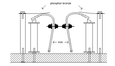
The next example is of a bit of provincial organ builders’ home brew from the 1930’s. Sketched in Figure 4, it was removed from an organ in the early 1960’s when the instrument was being overhauled, and because of the passage of time I no longer have this offensive item to photograph. It was a bistable relay which could assume one of two stable states and which was used in a reverser action, thus it mirrored the position of a reversible stop key on this instrument. Depending on which coil was energised, one or other of the phosphor bronze wipers was supposed to engage with the associated iron armature. The two armatures were coupled mechanically by the tapped wire and buttons as shown. The whole thing was merely mounted on a wood baseboard; there was no enclosure. Unsurprisingly, this and many similar items had failed completely long before their removal, and it was one reason for the overhaul of this organ. None of the reversers worked, including the Full Organ piston - you could press this and sometimes get Full Organ, but if you did it was a mixed blessing because it would likely not go off again. The instrument often remained in Full Organ mode even if you switched the wind off, and then you had to crawl inside the organ to reset the offending relay by hand. The mechanisms had become more or less immoveable owing to advanced corrosion of the ferrous parts, and corrosion had also prevented reliable contact being made between the armatures and the wipers. Who in their right mind would have used iron and phosphor bronze as contact materials? Even ignoring these defects, this contrivance showed no vestige of understanding of the concepts of efficient magnet design – the magnetic circuits were incomplete, and the cross sectional area of the armatures was inadequate for the flux involved. At a time when proper relays had been readily available for decades, can anyone explain why organ builders still persisted in their use of such crude and amateurish devices?
Appendix
1 shows how a pair of industry standard relays can be wired to perform the same
function, with much greater reliability and at trivial cost for those organ
builders who still like electromechanical actions (and there's no harm in that
provided they are realised professionally).
Figure
5. Home brew from the 1950's -
Compton's key contacts Moving on to look at some home brewed key contact arrangements, that in Figure 5 is of particular interest as it was used by Compton for both their pipe organs and the Electrones around the 1950’s, and it was encountered in the anecdote retailed earlier when discussing the peculiarities of silver contacts. The wiper was of phosphor-bronze, with a silver bar soldered across the end which touched the silver contact wires. In not a few cases the solder would spill onto the contact surface, thereby negating any benefit endowed by the use of the precious metal. The coiled return spring of phosphor bronze was retained at one end under a vertical hook which passed through a rebate between the keys, and at the other it was secured by the same screws which held the wiper. Thus the hook, spring and wiper were connected electrically, in theory. In practice many springs worked loose on these keyboards and they could not be tightened at the tiny fixing screws because these tended to lose their bite in the key. The hook, of brass or phosphor bronze, was threaded at its lower end and screwed into the rear keyframe member. Power was supplied to the row of hooks by threading a run of heavy gauge stranded wire under tension around them at the point where they entered the keyframe. Presumably by this means it was deemed unnecessary to use one or more contact wires in each contact block for supplying power, thereby enabling at least one extra circuit to be fed instead. However the fact that the power supply to each wiper relied on three points of connection of dubious reliability will have been noted. Whenever I have encountered key actions of this sort I have always improved the reliability by running an additional power bus to an unused wire of each contact block. Exactly the same thing was done by Robert Hope-Jones over a century ago - in his earliest patents c. 1890 he mentioned the need to ensure reliable operation (he called it "safety") by using redundancy techniques. But then, he was merely a professional engineer, not an organ builder if his critics are to be believed .....
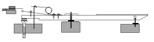
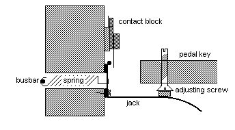
Compton's curious fondness for supplying power via the return springs was also seen in their pedal contact arrangements (Figure 6). The ends of the pedal keys were provided with adjusting screws each consisting of an inverted machine screw faced with felt. A screwdriver slot was cut in the top of the projecting shank. The felt disc operated a jack fashioned from thin tinplate or similar material bent into an L-shape, with the longer face formed into a curve. The shorter face was attached loosely by small woodscrews to a wood rail, curved to match the arc of the pedals. The jack was pulled against the rail by means of a coil spring running through a hole in the rail and secured on the opposite side by hooking it round a thick copper or phosphor bronze busbar. As well as anchoring the spring, this was the power supply common connection for all the jacks. A silver bar was soldered to the jack which touched the contact wires when the pedal was depressed. The contact blocks were identical to those used in the manual keyboards. Note that power was therefore supplied to the contact wiper independent of the contact block itself, as with the manual keyboards and presumably for the same reason: to avoid having to dedicate wires in the contact assemblies for power supply purposes. However in both cases the primitiveness of the arrangement as an example of electrical engineering will be noted.
Figure
6. More 1950's home brew - Compton's
pedal jack arrangement
Aside from electrical considerations, a convenience of the jack approach is that no electrical connections are necessary to the pedalboard itself which can therefore be removed and replaced easily. A disadvantage is that the touch can become deranged if the pedalboard rests on soft flooring such as a carpet, and re-adjustments may then be necessary. Thus another approach used by some builders was to mount the contacts on a curved rail underneath the pedal keys, at a distance from the rear fulcrum pins such that the amount of motion approximated to that of the manual keys to avoid straining the contact wires excessively. The rail was made as part of the pedalboard frame. In this case problems due to misalignment between the pedals and the jacks were removed once the action had been set up properly. However electrical connections had to be removed before withdrawing the pedalboard, and debris was apt to fall into the contact assembly. Not only dust but accumulations of paper, drawing pins, paper clips, pencils, erasers, confectionery, spiders' webs, dead insects and related detritus of the organ gallery would commonly be found when the contacts were removed. Willis was one builder using this method in the mid-20th century, for example in the organ at King’s College London. When it was overhauled in 1964 these problems were much in evidence. Yet another example of thoughtless design where contacts were expected to work indefinitely with no attempt to enclose them.
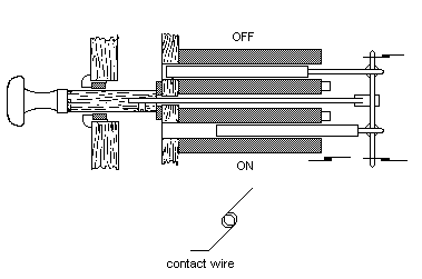
Now a look at draw stops. The obvious way to move a draw stop knob remotely is to use a single solenoid with two windings, so that the common armature will be pulled one way or the other depending on which coil is energised. However some builders have used two separate coils to achieve the same result. A sketch of the mid-20th century Willis mechanism of this type is at Figure 7.
Figure 7. The 1950's again - Willis's draw stop mechanism An advantage of this arrangement was that the depth of the unit behind the stop jamb was reduced compared to the single solenoid configuration, making for a slightly more compact console. The Willis all-electric consoles of this era were liked by some organists because of their standardised layout, and in this respect they were rather like the Wurlitzers beloved of theatre organists for the same reason. However they were crammed with home brewed electrical gadgetry which was not always as reliable as might have been desired, and some of it was excessively noisy in operation. Although the draw stop mechanism itself was not noisy, it was an example of Willis’s in-house design and it had several shortcomings. One was the lack of a toggle action, so that the knob often came to rest in some intermediate position if grabbed hastily or if the pistons were prodded too quickly. Thus one never knew whether the stop was on or off in this circumstance. Sometimes also the knob would bounce in response to the pistons, resulting in similar uncertainty. In addition the distance travelled by the knob was rather small, making it difficult to see at a glance whether a stop was on or off.
The electrical contacts were simply contrived from lengths of wire looped into a spring configuration as shown in Figure 7, and they were brought into contact with the rear wiper bar of the assembly. The two way contact arrangement shown in the diagram was generally used, in which one wire was permanently made to bear on the wiper – this was used as the common connection to the power supply. At the other end of the bar were the two contacts representing the ON and OFF states of the draw stop. These were sometimes connected to Willis’s electromechanical combination capture system as well as sending current to the slider machines. And of course, none of this was usually enclosed other than within the console itself. Such primitive switching arrangements were typical of those used widely in organs, and unless cleaned and adjusted regularly they could give rise to many electrical and mechanical problems.
Fig 8. More drawstop derangements
Much worse was the primitive contact arrangement (derangement?) sketched in Figure 8. This was encountered when I was asked to inspect the organ at St Mary's, Bradford Abbas in Dorset recently [12]. Again, it hailed from the mid-twentieth century. The organ was installed in the 1970's by a local builder, using drawstop mechanisms from an earlier instrument. Not shown in the diagram are the pneumatic means for moving the stops (book motors), suggesting that the entire action may have been pneumatic originally. Whether this was so or not, some organ builder at some stage had incorporated yet another abysmal example of home-brewed ideas of electrical engineering. The drawstop shank moved a horizontal pin between two pairs of phosphor bronze arms inserted into the rear framework of the stop assembly. The whole thing looked remarkably like a nail and a pair of hairgrips, and it worked no better. Because there was no mechanical toggle action on the stops, there was nothing to provide the pressure necessary to hold the contacts together when stops were drawn. Consequently it was unsurprising that speaking stops and couplers came and went at random, regardless of whether the stops were out or not.
So we see that even some of the most well known organ builders of the twentieth century, as well as a myriad of smaller ones, had for some reason turned their backs on the properly designed, well-proven, reliable and cost-effective electrical components used by the electrical and electronics profession at large. In summary, therefore, a century spent screwing bits and pieces of wire and phosphor bronze onto wood panels is scarcely something of which the trade can be proud. And with evidence such as that above, it is indeed a mere trade we are considering here, not a craft. So it is not surprising that some top rank organists still insist on the presence of an organ builder when giving a recital on an electric instrument - they have had their fingers burnt too often. (Sorry - I couldn't resist the pun). And perhaps it is not surprising that Williams and Owen have taken the view they have.
There is a widely held view that contacts with a wiping action will be more reliable than those which do not wipe. In fact all it does is to dislodge particulate contamination such as dust and grit, which would not have been there in the first place if the contacts were properly enclosed. In an organ, where even the most frequently used contacts are idle most of the time, a wiping action does virtually nothing to combat atmospheric reactions and contaminants on the surfaces. And, of course, the point where the contacts come to rest is where the current flow needs to be maintained. Unfortunately this is exactly where the wiping action ceases.
Wiping is unnecessary, and those who disagree are recommended to search for a commercial relay whose contacts use a wiping action.
We have mentioned that organ builders have relied on a modicum of sparking to keep their contacts clean, apparently oblivious to the fact that each time there is a spark the material is eroded. It was not unusual to find a wiper bar exhibiting grooves into which the contact wires sunk progressively more deeply before making contact. In extreme cases the wires could become trapped in these channels and the contact assembly then seized up. In other cases the wires themselves would disintegrate at the point of contact through erosion. And if the contact material was plated with gold, rhodium, silver, etc, any value this might have had was negated as soon as the plating had burnt through. Tolerance of sparks cannot therefore be seen in any light other than a further reflection of the amateurish nature of much organ electrical work.
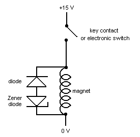
Sparks can be quenched to some extent by shunting the magnet coil with a resistor of typically 330 ohms; the resistor reduces the 'Q' of the resonant circuit represented by the self-inductance and capacitance of the coil and it provides a return path for the stored energy in the coil to dissipate once the energising circuit has been broken. However this is only a half-measure, a palliative rather than a cure, because the resistance of the return path is far too high. Around the 1950's some organ builders (e.g. Compton) tried using 'Atmite' discs across the coils; these were rudimentary voltage-dependent resistors whose resistance was lower the higher the voltage. However it is likely Compton's were driven to this because of their electronic organ interests, rather than because of a desire to suppress sparks per se. Without spark suppression, audible clicks would have been heard from the loudspeakers of their Electrones. (In the 1960's I had to abandon an attempt to make a recording of the Willis organ in the chapel of King's College London. Although this was of course a pipe organ, the radiation from the unsuppressed electric action was clearly audible on the master tape in the form of continual clicks and crackles!). Today it is even more important to suppress the high voltages which give rise to sparks when using today's electronic switching systems, because their transistors and integrated circuits are easily damaged otherwise. Therefore it is appropriate to discuss the matter further before moving on.
The reason why an electromagnet produces a high voltage kick when its circuit is broken is described in detail in another article on this website [8], and the use of a diode to absorb the energy is also explained there. Diodes are much more effective than resistors, though some maintain they prolong excessively the release time of the action. However the careful measurements reported in [8] suggest that the effect is unlikely to augment the release time by more than about 20%. Nevertheless, the addition of a Zener diode in series opposition to the ordinary diode can inhibit the reverse current through the latter once the initial high voltage has been quenched, thereby reducing any uncertainty about the matter. A Zener diode only conducts while the voltage across it exceeds a certain threshold, and the threshold voltage of the diode has to be chosen carefully to match the characteristics of the magnet being controlled and the transistor if the desired effect is to be attained. If the threshold is too high the circuit will not completely suppress sparks and dangerous voltages; if too low the beneficial effect of the Zener diode is negligible. There is not a single choice of Zener voltage which will suit all scenarios. The circuit is illustrated in Figure 9.
Figure 9. High voltage (spark) suppression using a diode and a Zener diode
Although conventional contact assemblies are still (2005) widely used and available, alternatives have come into use over the last 30 years or so.
Reed switches have been used, in which the contact itself is hermetically sealed inside a small glass tube and actuated by a permanent magnet attached to the key. By and large these are used more often on the pedals than the manuals, because of the hysteresis inherent in such a switch. Hysteresis means “lagging behind” and it refers to the phenomenon whereby the contact closes at a different position on the keystroke to that at which it opens. Where the movement is small, as on the manual keys, hysteresis means it is difficult to secure reliable operation – commonly the contact will not close at all or it will remain closed when the key is released. On the pedals with their greater movement, this problem is of lesser importance although careful adjustment is still necessary.
The switches themselves are fragile, and will fail early if not handled carefully. A common mistake in assembly is to bend the wires too close to the point where they emerge from the glass tube, thus cracking the glass. To prevent this the wires must be held in needle-nosed pliers before any attempt is made to bend them - it is surprising how many technicians do not do this. For the same reason, it is important to design printed circuit boards carefully so that no strain is put on reed switches when they are inserted prior to soldering. Another problem is that the switches are less robust than is sometimes supposed in adverse environments, because the contact springs themselves are necessarily made of some ferromagnetic material. If this material is also used for the lead-out wires (which it commonly is, even if gold plated), and if it corrodes easily, then the corrosion will eventually creep through the glass where the wires enter it and cause the seal to fracture via micro-cracks. Therefore reed switches have to be selected and used with great care. Today they seem mainly to find application in stop key and draw stop units as well as pedal contacts.
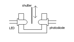
Other builders have employed optical sensors and Hall effect sensors, and standard sensor packages are used which are available widely from many sources. The optical sensor (Figure 10) consists of a light source and a detector, mounted in such a way that the passage of light from one to the other can be interrupted by a moveable shutter. The shutter is moved by the key and it therefore affects the amount of light falling on the detector, which in turn can be changed into an on/off signal by a suitable electronic circuit sometimes packaged with the device itself. The light source is commonly a light-emitting diode (LED), sometimes operating in the infra-red region of the spectrum, and the detector might be a photo-diode or a photo-transistor. The whole is mounted in a small and inexpensive plastic assembly. Sometimes the light emitted by the LED is pulsed at a certain frequency to which the detector circuit can be tuned in effect, thereby enabling it to reject non-modulated ambient light. The technology has benefited in terms of reliability and cheapness because of the development bestowed on it for use in equipment such as the ubiquitous computer mouse.
Figure
10. Typical optical sensor
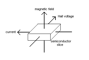
Hall sensors will be described in some detail because not all seem to know what the name actually means or how they work. They rely on the Hall effect, named after its discoverer E H Hall. If a current flows through a conductor with a magnetic field applied at right angles, a small voltage (the Hall voltage) will develop across one of the face-pairs of the conductor (Figure11). This is no different to the force experienced by a wire when it carries a current in a magnetic field, except in this case it is the charge carriers within the material experiencing the force, which therefore deflects them to one side. In practice a semiconductor material such as indium antimonide rather than a metal is used because the effect is more pronounced. The Hall voltage output is proportional to the magnetic field strength in all Hall sensors.
Figure 11. Illustrating the Hall Effect The slice is in practice minute and it is contained in the same integrated circuit package as the electronic circuitry necessary for the sensor to function. Small permanent magnets are attached to the keys instead of contact wipers, and the Hall sensors are mounted on a rail or a printed circuit board instead of the wire contact blocks. Hall sensors can be obtained in two varieties: those which either fully open or fully close an external circuit in the same way as an ordinary wire contact (Hall switches), or those which provide a gradual opening or closing of the circuit (linear Hall sensors). The difference is entirely in the type of electronic processing applied to the Hall signal, not in the sensor itself. The former variety is simpler to use and understand, but they require mechanical adjustment in much the same way as ordinary contacts so that the points of switch opening and closure can be made the same for all of the keys. Linear Hall sensors are used in some schemes which employ microprocessor control and which form part of an electronic transmission system (see [7] for example). In this case mechanical adjustment is not required as the microprocessor is “told” by the organ builder how the sensor outputs for each key are to be treated. For each key the processor remembers the Hall voltages corresponding to the chosen opening and closing positions of the key, just as if it was operating ordinary metal contacts. However the system is clearly not without its problems [13]. It can even be set up to have reverse hysteresis, in which the contact effectively opens at a greater depth of touch (when the key rises) than the value at which it closes (when the key falls). This is impossible with almost any other form of contact, though it seems to be more of the nature of a solution looking for a problem than anything else. Linear Hall sensors have also been used to measure key velocity in MIDI systems [7], presumably so that the keyboards of a pipe organ can operate touch-sensitive electronic instruments. They have also found application in a system which claims to enable the pallet to follow the motion of the key [9]. This system also uses magnetic “tracker touch” simulation. There is of course a much simpler and more artistic way to achieve these goals - it is called mechanical action.
Although contactless keying might be more reliable than using conventional contacts there is as yet no hard evidence gathered over an extended period to support this assertion. It may also be more expensive, and some of the more complicated systems may be at the mercy of rapid obsolescence. Also systems such as those described in [7] could only be serviced and maintained by the firm which provided them in view of their complexity and proprietary nature.
Electronic Switching and Transmission Systems
Switches in organs perform two types of function. The first is to close and open circuits in response to the player's operation of the keys and stops. The second is to ensure the resultant currents are routed appropriately within the organ. Therefore the key and stop contacts in the console fall within the first category; coupler relays, reversers, unit chest selectors and similar switches deeper inside the organ fall within the second. Thus far we have not distinguished formally between these, as the functions of the various switches under consideration should have been reasonably obvious from the context of the discussions. We have already covered the ordinary wire-and-wiper type of contact as well as the more recent contactless varieties. Now we shall concentrate explicitly on the second function category defined above, in which switches are used inside the organ to perform various routing and logic functions on the signals received from the console. We shall also dwell exclusively on the use of purely electronic techniques for implementing these functions rather than electromechanical devices such as relays.
Purely electronic switching has been used in organs since about the 1960's when transistors started to become more robust and cheaper than hitherto. It is important to bear in mind that electronic logic switching can be used with both conventional wire-and-wiper contacts and those using contactless sensors at the console. Unlike their electromechanical counterparts, electronic switches contain no moving elements and this has led to a widely held view that they will therefore be automatically more reliable. However this view is simplistic if only because it has not been quantified for the organ paradigm. Reliability is a formal discipline to which the industry at large diverts vast resources, and a professional engineer will only use the word in the proper context. The point here is that reliability means nothing if it cannot be quantified. Electromechanical devices such as relays are sold with a life expectancy of so many operations (typically in the tens of thousands). Where are the corresponding data for the purely electronic analogues used by organ builders in their organs? They are not quoted, and until they are it is quite misleading for them to claim that these products are "more reliable".
Some representative circuits will now be discussed, but there are many variants and it should not be assumed that the circuits here are the only ones possible. To begin the survey, a basic transistor switch is shown in Figure 12.
Figure 12. Basic transistor switch
Instead of the magnet being controlled directly by a contact, it is placed in the collector circuit of a transistor and the contact itself now provides current into the base circuit. The most important advantage gained is a large reduction required in the current required to operate the magnet. If it is a chest magnet as used in an electro-pneumatic action, the magnet itself would draw about 100 mA when operated at 15 volts as in the diagram. But because a typical transistor could have a current gain around 100, the current drawn through the contact would be only about 1 mA. A larger magnet as used in a direct electric action would require about 500 mA, and the current switched by the contact would then be 5 mA or so. Current gains much larger than this can be obtained using different types of transistors. These much-reduced values for contact current, together with the isolation provided by the transistor between magnet and contact, mean that there is no longer any sparking problem to contend with. If optical or Hall sensor switching was used at the keys these could quite possibly supply the current required, whereas they certainly could not if the transistor was not interposed between them and the magnet coil. Although there is no longer a sparking problem at the contact, note the continuing need for a suppressor diode to prevent the transistor being damaged by the large back emf when the magnet is switched off.
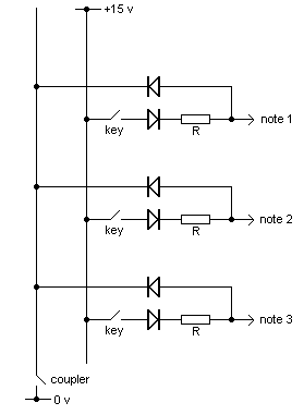
Because of the small currents flowing in the base circuit, it also becomes possible to perform a number of useful binary logic operations at this point in the circuit. Figure 13 shows how a set of AND gates can be realised from diodes and the resistors marked R, and this type of logic is used for couplers.
Figure 13. Diode AND gating for 3 note circuits and a coupler
Three gates are drawn here, each with two inputs. One input to each gate is a from a key contact, whereas the other one is a common input from a switch which might be an inter-manual coupler such as the Swell to Great. Each gate only gives an output when the key contact is closed AND the coupler contact is open, hence the name given to the gate. Therefore the two types of contact operate differently - the keys are on (active) when their contacts are closed, whereas the coupler is on when its contact is open. This was done merely to prevent cluttering the diagram with additional complication, although it is easy to make the two types of switch operate in the same way. Thus by closing the coupler switch in this example, no note outputs will be obtained regardless of which keys are pressed. The note outputs from the coupler gates pass to further logic circuits, or directly to the bases of a corresponding set of transistors. For obvious reasons this type of switching circuit is often called "diode keying". A set of 61 AND gates performs the same function for five-octave keyboards as the large inter-manual coupler relays (ladder switches) with 61 contacts originated by Hope-Jones, which have been used for over a century in electromechanical switching systems.
With many couplers and several manual departments plus pedals it will be obvious that the system can get quite complex, involving hundreds if not thousands of diodes and transistors. Although there are no moving parts in a diode keying system, it still has a number of potential reliability weaknesses. One is simply due to the large number of components because the reliability figure for a single transistor or diode will clearly be reduced for the system as a whole, and there are well established rules for calculating what the MTBF (Mean Time Between Failures) will be for the complete assembly. It is interesting to speculate how many organ builders know what the MTBF's are for the systems they incorporate into their instruments. A further problem is that electronic switches are more electrically fragile than electromechanical ones in the sense they are less tolerant of high voltages. These can arise from lightning discharges, which cannot be discounted in tall buildings such as churches. Even nearby strikes which do not hit the building itself may still result in damage to the electronic switches in an organ. Some cautionary tales were retailed in [3] relating to this problem.
Another source of unreliability and expense in a diode keying system is the need for lots of cabling and soldered joints, and in this respect these systems are little different to their electromechanical counterparts. However it is possible to design them so they need only a single contact per key rather than the multiple contacts which characterised the earlier systems. Nonetheless several cable looms are still required between the keyboards and the circuit boards containing the diode keying components.
" ... it's not a subject that has much interest for organ builders ... " Ian Bell
Thus electronic switching systems moved a step further when they used multiplexing techniques to scan the console contacts, sending the resultant signals down just a few wires (or even a single pair) to the organ itself. This is not the place for a detailed discussion of multiplexed transmission systems as I have written at length about them in [3]. That paper pointed out several shortcomings including cost - despite needing far less in the way of cabling and therefore labour costs, and despite what manufacturers often claim, these systems are certainly not cheap. That for the rebuild of the Harrison organ at All Saint's Margaret Street in London ran to £20,000 exclusive of VAT [10] ! One could buy a useful amount of pipework for that sort of money. There have also been too many embarrassing and high profile examples of partial or complete failure, some of which have been mentioned elsewhere in this article. Repairability, obsolescence and scanning delays are other potential shortcomings. Therefore the somewhat cosy embrace between today's organ builders and the manufacturers of these systems has not yet removed the problems which tend to be associated with electric actions in the minds of many, indeed it has added new ones.
On the whole organ builders, including some of the best known, seemed far more at home with mechanical rather than electrical work during much of the twentieth century. Judging by the poor quality of some of the electrical items still used, there remains some truth in this view today and consequently it is not unfair to regard their approach to electric actions as little more than amateurish right from the start. Many of them also seem content to use complicated and expensive solid state control systems with apparently little understanding of what goes on inside and what the implications for the customer and player might be. That certain items are potentially lethal beggars belief. It is curious that electricity in organ actions is singular in that it is the only aspect of the trade which some organ builders think does not require a professional approach.
This situation has resulted in a deserved reputation for unpredictability and capriciousness in electric actions, a statement which can be amply justified by example. So at the end of this article we might return to the condemnatory remark of Williams and Owen and ask whether it does indeed stand up to scrutiny.
Relating to the following Appendices, if you do not have sufficient understanding of and experience with electrical and electronic circuits, you should not proceed or act in any way on what follows. It is emphasised that use of any material presented here is entirely at your own risk.
In the case of Appendix 1, should there be any doubt, all of the circuits to be described operate on DC not AC, and the polarity (positive and negative) of the applied voltage is important in all cases, even when using relays. Although the voltages are low, the currents available from organ power supplies are considerable and there is a potential risk of damage, including that caused by fire, if circuits are improperly constructed or installed or if fault conditions arise. It is prudent to include fuses in the power supply lines feeding each circuit or group of circuits in an organ so that any fault currents will be of short duration. The current rating of each fuse must be determined by the load it feeds, and this must be the responsibility of the system designer. Wiring must be carried out in accordance with the appropriate wiring regulations, which in the UK are issued by the Institution of Engineering and Technology (the IET, formerly the IEE).
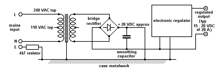
Appendix 2 relates to a potentially lethal organ power supply unit, and professional advice should be sought if you think the problems described might affect your organ.
APPENDIX 1 - Representative Circuits using Industry Standard Devices
Before reading further, ensure you have seen the hazard warning above relating to these Appendices.
In this Appendix we look at some circuits using industry standard devices rather than the usual organ-specific items sold by organ builders' supply houses, some of which are wonderfully bizarre, badly made and expensive for what they are. Not only is the former approach more professional, but the component cost will be reduced by a large factor and reliability will similarly increase. Both electromechanical and fully electronic circuits are discussed.
Reversers
Reverser circuits are good subjects for discussion because they are sufficiently complex to enable a number of different aspects to be illustrated. They can also be made in many different ways, even when ignoring (as we shall) the peculiar devices sold specifically for the purpose.
A reverser circuit reverses the position of a stop key or draw stop when a piston is pressed. It can also be used for Full Organ reversible pistons and similar purposes. In formal terms a reverser (including the motorised stop key or draw stop unit itself) is a presettable binary counter circuit, which divides the incoming "frequency" from the piston by two. This is because the piston has to be pressed twice for the stop to return to its original position. The circuit must recognise and respond to four distinct states, which are: piston off/stopoff; piston on/stop off; piston off/stop on; and piston on/stop on. The heart of the circuit is a bistable latch, which is able to remember the former state of the stop (on or off) while the piston is pressed and while the stop itself is changing to the new state. When the piston is released the latch then changes state to reflect the new position of the stop. The latch must also change state if the stop is moved by hand.
The circuit must be designed robustly so that it will not fail when, for example, people fool about with it - it is depressing that it is not always children who want to see what happens if they prevent the stop moving while pressing the piston, or who deliberately jab at the piston like a maniac until something goes wrong. Nor must the prevailing state of the stop be affected when the organ is switched on or off, otherwise those organists who like to leave the Pistons Coupled stop drawn will be frustrated. Also the circuit must be reasonably tolerant of the indifferent quality contacts found on many pistons, though there are limits to what can be done in this regard and occasional malfunctions will almost always be due to contact problems at the piston.
In general counter circuits (especially fully electronic ones) often seem at first sight to be more complex than they need to be, but there are two main reasons for this: firstly they have to be robust to what are called "races", and this is also true when using relays. In relay circuits races occur when two or more relays are changing state simultaneously, and during this period the behaviour of the circuit is undefined. If races are not controlled in some way the circuit will likely malfunction because its behaviour will usually depend on which of the contacts happens to close or open first, and often this is governed more by chance than design. For the fully electronic counters used in computers etc, it is important to get the maximum possible operating speed out of the circuit and in this situation race analysis is extremely difficult and a specialisation all its own. It usually implies including several if not many additional gates (equivalent to extra relay contacts), and these can be seen when looking at the internal circuit diagrams of commercial integrated circuit counters. When extreme speed is not an issue, as here, races can be controlled quite simply by slowing down the operation of the circuit so that events occur in a controlled and sequential manner. With a reverser, races will not occur if the latch circuit is properly designed and if it works faster than the stop unit itself. This is generally not difficult to arrange if the stop unit employs mechanical movement as with ordinary stop keys or draw stops, because the time required for the stop to travel between its on and off states is significant. It is more difficult if the stops use illumination to indicate their state to the player, when the circuitry controlling the lamp or LED will be faster than the relays used in an electromechanical reverser.
The second reason for the apparent complexity of reverser circuits is that reliable latches themselves employ a number of logic elements (gates), whether the circuit uses relays or electronic gates.
Electromechanical Reverser Circuit using Two Relays
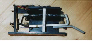
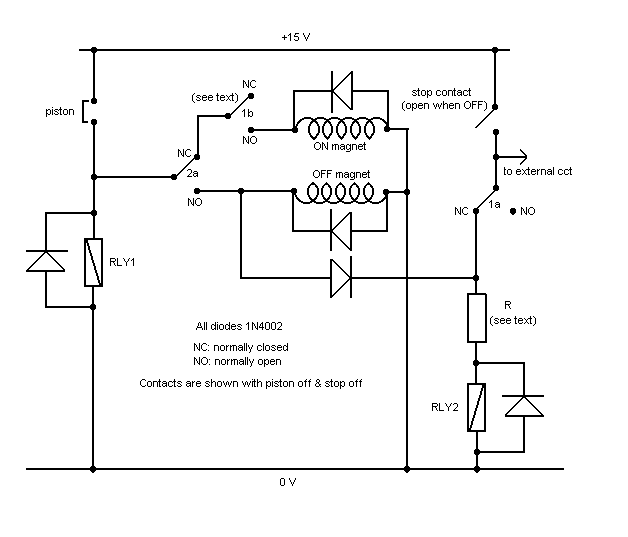
The circuit of a reliable and economical reverser using two ordinary relays in addition to the stop unit itself is at Figure A1 below. It is assumed here that the usual motorised stop key or draw stop is used which has two magnet coils and a single switching contact, which in this example will be assumed to be open when the stop is off and vice versa. However the magnet coils and the switch must be electrically separate, which means that certain brands of stop unit might need some minor rewiring. For example, the widely used though now obsolescent SKH style of stop key unit by Kimber Allen (pictured below) was sold with all three returned to the frame of the assembly. To make this unit suitable for use with this circuit it would be necessary to disconnect the two magnet returns at this point and solder them to a separate bus. (Alternatively the circuit could be altered but this will not be discussed here). Most if not all modern stop units will not require this modification because they use reed switches which can be wired as required, rather than mechanical switches using the magnet frame as one pole of the switch.
Above - Kimber Allen type SKH stop key unit
Figure A1. Electromechanical reverser using two standard relays
The two relays RLY1 and RLY2 are assumed to have 12 volt coils with a resistance around 150 ohms, though these values are not critical. In the circuit as drawn, RLY1 requires two sets of contacts, denoted 1a and 1b in the diagram, and RLY2 requires one, denoted 2a. However the contacts 1b were included as an additional precaution against races and it will usually be possible to omit them, thereby making both relays identical each with a single set of changeover contacts. The function of 1b is to ensure that the stop unit does not change state before RLY1 has done so, but since the relay will almost always be faster than the stop unit itself this should satisfy the race criterion automatically.
The abbreviation NC (normally closed) means that the contact is closed when the relay is not energised, and NO (normally open) means the contact is open in the same situation.
A resistor R is shown in series with the coil of RLY2 because the circuit was designed to operate at 15 volts whereas 12 volt relays were assumed. This resistor will typically be 36 ohms/0.25 watts for a 150 ohm relay coil, and it drops the voltage appropriately. It is not really necessary to use a resistor for RLY1 in this case because it is only energised momentarily while a piston is pressed. Note that the resistor R will need to be different from the value mentioned if different operating voltages are used, or if the relay coil has a different resistance. The value of R in ohms is given by
R = (VS - VR)RL / VR
and its power rating in watts is given by
W = (VS - VR)VR / RL
where VS is the supply voltage in volts; VR is the relay coil voltage in volts; and RL is the relay coil resistance in ohms.
There is a wide range of relays which would be satisfactory for this application, some of them very small and costing well below £1 each. In the UK the catalogues of professional component distributors such as Rapid Electronics Ltd, RS Components Ltd or Farnell should be consulted for relays which will suit the intended application in terms of operating voltage and physical size. A contact current rating of 1 amp should be suitable for most types of stop unit, and silver contacts will be satisfactory. It would be inadvisable to use relays with current ratings below 1 amp. The faster the relay, the better. It is important that spark suppression diodes are fitted as shown in the diagram if the relays are to have a long life. Using BT47-style relays will result in virtually noiseless operation, although this will also be true of many other types today.
Fully Electronic Reverser Circuit Type 1
Designing fully electronic circuits which will work reliably in an organ over many years without maintenance is surprisingly difficult. One problem is that the circuitry itself is intrinsically very fast whereas it has to be interfaced to slow, almost 'agricultural' devices such as draw stop solenoids. Thus the slightest vestige of the repeated pulses (called contact bounce) which often occur when an ordinary contact is made or broken, such as that in a thumb piston, will be treated as a string of new pulses by the electronics and they will frequently result in a variety of surprising or annoying consequences. One is that a stop will correctly move to its new position when you press a reversible piston, yet it might jump back again when you release it. These problems are less severe with relay circuits because the relays themselves are much slower in response and their coils require significant power, thus rogue pulses of fleeting duration are less likely to affect the state of the relay. Consequently quite elaborate precautions have to be taken to ensure that electronic circuits are completely proof against contact bounce.
Another issue is that the susceptibility of the circuits to radio frequency (RF) interference from mobile phones, radio microphones, etc must be considered. Otherwise an organist can find stops jumping in and out whenever an inconsiderate member of the congregation sends a text message, or when the vicar ascends the pulpit to begin her sermon. An organ designer who has not yet encountered such problems can expect to find life getting more exciting. Yet another factor is that the devices used to implement the circuit logic, unlike relays, are usually incapable of driving the magnet coils directly. Therefore additional devices have to be included for this purpose. Solutions to these problems will be illustrated by considering a fully electronic counterpart of the electromechanical circuit above.
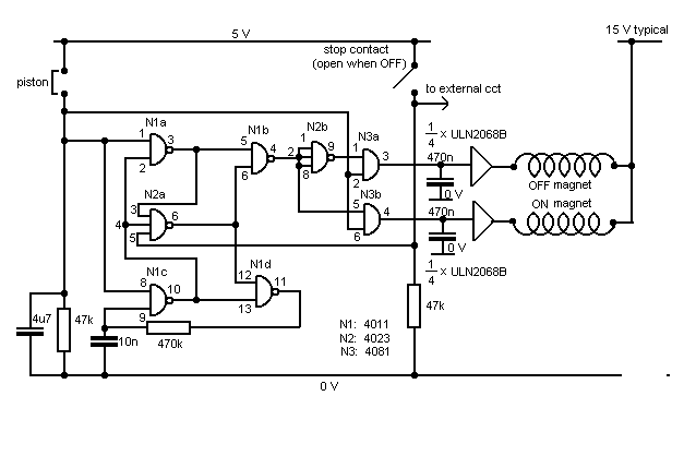
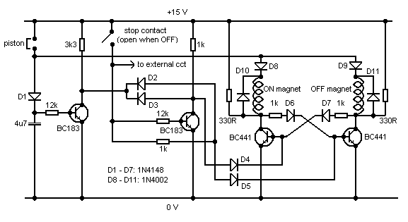
An example of many possible electronic reverser circuits is shown at Figure A2. This one has the undeniable advantage that I have made a number of them and they have worked entirely reliably for two decades without maintenance. It uses three ordinary CMOS 4000-series integrated circuits, plus half of a quadruple Darlington driver package for supplying the heavy current to the stop magnets. Additional inputs to the magnet drivers from an electronic combination capture system can be arranged if necessary, if the stop is also required to be part of the combination system (often it will be). However this is not shown here as it would complicate matters further. The logic of the latch part of the circuit is due to the late Dr A D Ryder [11].
Figure A2. Fully electronic reverser circuit Type 1
To avoid obscuring the wood by the trees, some features are not shown on the diagram. Points to note are:
1. Unused gate inputs of the CMOS packages must be tied to the 5 volt or 0 volt lines. 2. The CMOS packages must work on a regulated 5 volt supply, not the 15 volt magnet supply. 3. The ULN2068B package must be supplied with a voltage Vs (see the data sheet), typically 5 volts. 4. No suppressor diodes are needed across the magnet coils as these are incorporated within the ULN2068B chip. 5. The ULN2068B must also be supplied with the 15 volt line to provide a return path for its internal suppressors. 6. It must also be supplied with the 0 volt line to provide the return path for the magnet coils.
Thus the data sheets for all the devices mentioned should be consulted before using them. It should be noted that all of them have been available for several decades and they can be considered to be industry standard components. Should sourcing difficulties arise in the future, a range of alternatives is likely to be available for the foreseeable future in view of the large numbers still used across the electronics industry.
Because the piston is shown working at only 5 volts a silver contact would be unreliable for the reasons discussed in the main text. Gold would be satisfactory but for the presence of the 4µ7 electrolytic capacitor, which is necessary to assist with contact debouncing and RF interference removal. The repeated charging of the capacitor might degrade the gold surface over time. Phosphor bronze would be little better than silver and quite likely worse, thus for all these reasons it is best to interface the piston to the reverser itself using an additional buffer circuit. A small reed relay might be used, but I prefer to use the electronic buffer circuit shown at Figure A3. This has enabled quite poor quality piston contacts to work reliably over periods of many years without requiring any maintenance. It was the circuit used to solve the problem mentioned in the main text relating to the pistons on Compton keyboards when these had been converted to electronic operation.
The buffer applies around 15 volts to the piston contacts, derived from the supply used to drive the magnet coils, but reduces it to 5 volts to suit the logic devices in the reverser. Because it uses a transistor amplifier, the make and break transitions of the contact are also speeded up and this much reduces the problems of contact bounce. The transistor can be any general purpose low power silicon PNP device such as the BC213.
Figure A3. Piston buffer circuit
Fully Electronic Reverser Circuit Type 2
To show how different an alternative but still fully electronic arrangement can be, we shall now look at the circuit of Figure A4. This uses four discrete transistors instead of integrated circuits, and two of them are chosen to be capable of driving the stop magnets directly. This removes the need for additional Darlington driver packages. Although this introduces a simplification compared to the previous design, one disadvantage is that separate suppressor diodes are now necessary across the magnet coils.
Figure A4. Fully electronic reverser circuit Type 2
The circuit again uses a bistable latch, but one in which the logic is implemented with diodes in the same way as in diode keying systems. Such a simple approach could not be used if the circuit had to work very fast, but for a reverser it is perfectly adequate. No special requirements are placed on the type of piston contacts in this case as they work at 15 volts. Thus silver or even phosphor bronze will be generally reliable, though not completely infallible. Even the best circuits cannot always compensate for poor contacts. The circuit will not work arbitrarily quickly, in other words if you repeatedly jab at the piston, you will find the stop ceases to respond beyond a certain repetition rate (this is also true of the Type 1 circuit). This is deliberate and a result of precautions taken to reduce the effects of contact bounce. It arises because of the time constant in the piston circuit created by the voltage on the 4µ7 capacitor decaying through the 12k resistor. However the response is adequately fast for all musical purposes.
The circuit is designed to sink about 0.5 A through the magnet coils, and this should suit a wide range of stop units which commonly have a magnet resistance around 30 ohms. The transistors specified will handle more current if necessary, though this is not recommended. The reason is that the transistors have quite a low current gain, therefore the currents through the diodes feeding the base circuits can become excessive if too much collector current is drawn. The transistors do not require heat sinks provided the piston will not be held in for unreasonably long periods, but to guard against the possibility of the piston jamming in the ON position the provision of heat sinks would certainly do no harm.
Other Circuits
One could go on for ever describing innumerable variants of reverser circuits. A third fully electronic option would be to use the bistable latches available in integrated circuit form, such as the CMOS 4042. This package contains four latches which might be convenient if there are several reversers on the organ. However each reverser circuit will still require additional packages such as AND gates and Darlington drivers.
With a software-controlled combination system incorporating microprocessors the complexity of the external circuitry will be somewhat reduced, though Darlington drivers will still be required for each magnet. Effective contact debouncing can also be as awkward and tricky with software as it is with a hardware approach, and often it is more effective to use a few external components to reduce spurious pulses before feeding them into the computer system.
Which circuit is best?
There is not much to choose between the two fully electronic circuits described here in terms of complexity, because although Type 2 only uses four transistors its wiring diagram is still fairly involved. However, in general it is always preferable to use integrated circuits in preference to discrete devices such as diodes to implement the circuit logic. This is because of the very careful and highly optimised design of the circuitry within the IC packages, thus designs using discrete components just cannot compete. Therefore the Type 1 circuit is marginally preferable to Type 2. Type 1 is also easier to interface to a combination system.
But if a basic stand-alone reverser is sufficient, the relay based circuit described here is hard to beat for cheapness, ruggedness, simplicity and maintainability.
APPENDIX 2- An example of dangerous practice
Before reading further, ensure you have seen the hazard warning above relating to these Appendices.
In the 1970's, and possibly later, a well known UK supplier of electronic (solid state) organ components and control systems was marketing a mains driven DC power supply unit which was dangerous in the sense of being potentially lethal to anyone working inside the organ, and even to the player in some circumstances. It is possible that some organs, not only in the UK, are still using this brand of power supply, and therefore it is suggested that steps are taken to ensure that the units incorporated into any organ in which you have an interest are examined by an independent electrical safety consultant with the appropriate accreditation (who should not be the supplier of the equipment nor the organ builder to ensure impartiality) to ensure they do not suffer from these or similar defects. Apart from anything else, using equipment with the defects to be described could affect insurance policies for the buildings concerned.
The circuit of the unit in question is sketched schematically below. It supplied a regulated voltage which could be adjusted within certain limits depending on the model number (e.g. between 15 and 20 volts DC at up to 20 amps). Because the output voltage was electronically regulated, it remained virtually constant regardless of the current demand. (Note this is different to simpler types of power supply which do not use electronic regulation, and whose output voltages therefore vary considerably depending on the current being supplied).
Power supply schematic wiring diagram showing general electrical arrangement
In my opinion, the chief concerns thrown up by this unit are:
1. The 3-pole mains input connector was of a type now illegal, at least in the European Community, and before that it was an unrecommended type for many years. Its safety problems relate to the fact that it has no satisfactory means of cable support and clamping. Anything beyond the mildest strain on the cable would result in its partial or complete detachment from the input socket, quite possibly with the exposure of live mains conductors. The connector is shown below.
Dangerous mains input connector
2. Contrary to what might have been expected, the metal case was not grounded (earthed) directly to the corresponding pin of the mains input connector. Instead, it was grounded to this pin via a 4.7 k resistor in the example I examined, as shown in the photograph below. The arrangement is also sketched in the schematic wiring diagram above.
Ground connection to case via 4.7k resistor
This could result in the following consequences:
There was therefore the potential for the case of the unit to become live and remain live. Because of the design of the unit, this would also mean that the entire low voltage electrical system of the organ would become live also. The implications are described below in 5.
3. An unused mains tapping of the transformer (used to adjust the unit for different mains voltages) was stored dangerously inside the unit, by merely being clipped alongside a cable loom (pictured below). Not only does such practice put engineers and technicians at risk, but the wire in question could work loose and contact the case which would then become live. By virtue of 2 above, there is no guarantee with this unit that the resulting ground fault current would result in the mains supply being removed automatically.
Unsafe unused tapping on mains transformer
4. The unregulated positive pole of the DC supply was connected internally to the case. Typically this voltage was around 28 VDC, depending on model number. Therefore the full unregulated voltage from the bridge rectifier would be shorted out if a short circuit occurred between the negative output terminal and the case. These points will be better understood by referring back to the schematic wiring diagram above.
One way this could occur is via the ground leads on test gear being used within the organ during installation, or while fault-finding in the electrical system. Another would simply be accidental contact between the case and the negative terminal. In these conditions a current typically in excess of 20 amps would flow for an indefinite period. In turn, this could cause overheating of the rectifier and mains transformer with a number of possible consequences, including its developing a ground fault. This would then have the further consequences described in 2 above. Even if this did not happen, other forms of damage (including fire) could result because the consequences would be similar to accidentally short circuiting the terminals of a car battery in view of the high current involved.
5. Although neither of the external output terminals were connected directly to the case, they would nevertheless become live with the case itself under mains fault conditions. This is because the unregulated positive pole of the DC supply was connected internally to the case as described above. Therefore the entire low voltage system of the organ would also become live in these circumstances, with obvious serious consequences for anyone touching any part of it. This could even happen to an unsuspecting player if certain types of control were used at the console. For example, the moving metal caps of toe pistons are often in electrical contact with the low voltage supply and therefore the pistons themselves would be at mains voltage in these circumstances. Or the metal bearers under certain types of stop tab are also often in electrical contact with the supply, and it is easy to touch these when operating the stop keys.
6. This unit had an auxiliary output socket for driving a subsidiary power supply unit to increase the maximum current available. Both mains power and low level control signals were routed through this socket. It was noted that the live mains conductor to this socket used brown wire (correct, at least in the EU) but so also did the low level control line. This represents poor practice, verging on the dangerous, in view of the ease with which these leads could be confused by a technician or service engineer. The two brown leads in question can be seen at the top of the picture above which also depicts the 4.7k grounding resistor.
7. Other examples of poor design and assembly were the omission of heat sink compound between the output transistors and their heat sink, thereby increasing the risk of transistor failure in use. Also the intended electrical path between the unregulated positive output from the rectifier and the transistor collectors relied purely on the case itself and a number of steel self-tapping screws. In my unit some of these had corroded to the extent of having sheared off, thereby rendering the connection dubious. It is likely that the corrosion itself had been caused by the current flow.
It is astonishing that such a unit could ever have found its way to the market. It was potentially very dangerous, and it possessed a number of faults suggesting unprofessionalism amounting to incompetence on the part of those involved in its design. Unfortunately it just emphasises yet again the amateurish nature of much organ electrical equipment, and the low level of competence in some parts of the organ electrical trade.
1. "Hope-Jones and the Dry Cell", C E Pykett, 2003. Currently on this website (read).
2. "Hope-Jones at the College of Organists", C E Pykett, 2004. Currently on this website (read).
3. "Electronic Transmission Systems", Colin E Pykett, Organists’ Review, August 1999, p. 220. Also currently on this website (read).
4. "Soundboard", John Norman, Organists’ Review, November 1999, p.316.
5. Remarks by Christopher Gray, BIOS Reporter, January 2003, p.11.
6. "Relay Technology - Fundamentals and Related Developments", Matsushita Electric Works UK, 2004.
7. "Look – No Contacts", D Levy & J Norman, The Organbuilder, November 1999, p. 22.
8. "Response Speed of Electric Actions", C E Pykett 2004, Figure 2 et seq. Currently on this website (read).
9. "A Proportional Electric Action for Slider Soundboards", P Robert, The Organbuilder, Vol 16, 1998.
10. "All Saints Margaret Street London W1 Organ Restoration Appeal", pamphlet c. January 2000.
11. "Stop Control", A D Ryder, Wireless World, March 1979, p. 57.
12. "The Organ at Bradford Abbas Parish Church, Dorset", C E Pykett, 2004. Currently on this website (read).
13. "Some recent rebuilds and restorations", Roger Fisher, Organists' Review, May 2005, p.123.
14. "Fault silences Albert Hall's organ after £1.7m refit", David Stringer, The Independent, London 26 July 2004. (When this article was posted in 2005 the piece was available at Independent, The (London) Fault silences Albert Hall's organ after pounds 1.7m refit. However the link was broken on 21 December 2009).
15. See http://www.nottinghamchurches.org/organ/brochure.pdf (accessed 16 May 2010; not found 24 October 2010).
16. "Made in Manchester", BBC2, 1999. (The Bridgewater Hall organ by Marcussen was most definitely not made in Manchester!).
17. "There are plenty of organs whose fuses could be expected to blow if fed with Ligeti's 'Volumina', but the Festival Hall is the last place you would expect it to happen: absurdly it did last night. 'Volumina' began with a deafening bravado - a huge tone cluster using every stop in sight. Then silence, but for the glances - positively vocal in their astonishment - between M. Daresse and his two assistants. Explanation: the current had been overloaded and caused a sudden flood when all the notes were released, blowing the fuses responsible for the electro-pneumatic contact between notes and pipes. Apology: no Ligeti". Financial Times, 1971. |