


|
|
|
The Calculation of Pallet Sizes by Colin Pykett
Posted: 19 August 2001 Last revised: 17 December 2009 Copyright © C E Pykett
Abstract. Calculating the windway area of an organ pallet valve which is necessary to supply a given set of pipes without robbing is not straightforward. It is important to use the smallest value possible if pluck is to be minimised, rather than to rely on conservative design rules which may result in excessive values. Once the necessary value has been arrived at, the pallet can then be designed using standard long/thin valve theory. This paper summarises the results of some experimental work in this area.
Contents (click on the headings below to access the desired section)
Calculating the size of a pallet to supply a given set of pipes can be done once the pipe dimensions and wind pressure are available, so that the quantity of wind they will require can be estimated. However, since the pipe dimensions also dictate the soundboard layout in terms of bar separations etc, it is perhaps not surprising that the pallet sizes are often derived as a by-product of this process rather than from considerations of air flow. Depending on the resulting pallet size, which will of course vary across the compass, the use of pneumatic or electric helpers may then be required in mechanical actions to relieve the touch. (An alternative design philosophy has been proposed by John Norman 1 in which a standard design of pallet and action is used to confer uniformity of touch in a mechanical action organ, with the additional wind demands in the bass being met by off-chest pneumatic servo valves. This approach will not be used here). It is apparent that there is still a degree of uncertainty about the best way to design pallets. Otherwise we would not have recent mechanical action organs which have needed electric assistance to additional pallets included apparently as an afterthought, or those in which wind pressures are too low so that they remain playable but otherwise ineffective, or those in which there is robbing when all the stops are drawn. To investigate the problems some research was done covering all aspects of the matter, but entirely from the viewpoint of wind demand rather than the geometry of pipe plantation : firstly the wind demand of representative pipework was addressed, then the phenomenon of robbing itself, then the design of pallets to cope with the demand without causing robbing, and finally methods for relieving the touch of large pallets. However the work in the last area is not reported here as it appears elsewhere on this website 2 . The paper addresses the major design issues in as simple a manner as possible, and from first principles - it was assumed that a pallet had never been designed before. Therefore existing design rules, theories, design aids and rules of thumb are deliberately not reviewed except in one or two instances, where they are tested against new experimental data. There are three apertures relevant to this study through which wind must pass in series: the first is the windway of the pallet, the second is the physical pallet aperture (the two are not the same), and the third is the exit or load aperture presented to the pallet by the combined pipework standing on its groove. The key to effective design is to ensure that all of these are explicitly addressed and stand in proper relation to each other. An added bonus of careful design is that the pallets will not be any larger than necessary to satisfy the wind demands of the pipes, thereby minimising pluck and hence the need to employ touch relieving devices unless absolutely necessary. The work described in this paper is largely experimental because modelling gas flow through apertures, especially a sequence of apertures, is complex – unfortunately there is no simple analogue of Ohm’s Law for electrical circuits. This is because any concept of "resistance" due to an aperture is not constant but varies with flow rate, pressure, aperture shape and whether the flow is turbulent. Thus the mathematics involved at once becomes non-linear, and only approximate theoretical solutions can generally be derived. It is this which explains the continuing need for expensive test facilities such as wind tunnels in aerodynamic research even with today’s computing power. In the end, everything involving air flow has to be derived or checked experimentally if we want to get it right, whether in aviation, air conditioning or organs. In this study an experimental strategy was devised which avoided the need to measure air flow rates, which is difficult without disturbing the flow when both flows and pressures are as small as they are in organ work.
If all pipes are available, regulated and voiced before a soundboard is designed, it is not difficult to estimate the total load aperture presented to a pallet. For each flue pipe, the smaller of foot hole area or flue area is taken and the results added together for all pipes for a given note. (Reeds are more difficult, but the total wind demand is usually dominated by the large flues). This will give an approximate value for load aperture, although even this simple process of summing areas is not generally permissible in aerodynamics 6 . However, we have to start somewhere! In this study an attempt was made to generate a representative generic model for the apertures of various flue ranks, but based on experimental data. The model was used to test subsequent stages of the pallet design process without tying the results too closely to a particular organ.
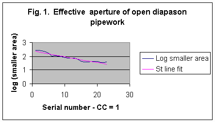
A set of measurements was first made of flue area and foot hole area for the lowest two octaves of a great organ open diapason (8’), voiced, regulated and installed in a respectable-sounding church organ. Although the pipework was of no particular pedigree, it had the advantage of being in generally excellent condition thereby facilitating accurate measurements - foot holes were nicely circular, and flues rectangular. For each pipe the smaller of foot hole or flue area was taken, and the values plotted graphically. The values increased sharply towards the bottom note as would be expected, but by plotting the logarithm of area the data fell quite close to a straight line (Figure 1). This gave some confidence that the values could be used as the basis of a simple model for further use. The purely empirical equation of the straight line was: log10 y = 2.4 – 0.043n (1) where y is the pipe windway area (mm2), i.e. the smaller of flue or foot hole area; and n is the serial number of the note (n = 1 for CC) By extrapolating the line down an octave, an estimate of windway for a 16’ diapason rank of similar scale could be obtained. As a "health check" on the results, the area (about 745 mm2) so obtained for the CCC pipe was examined, which could give a flue orifice some 212 mm by 3.5 mm. This might seem rather ponderous for a manual double, but it was used for reasons to be mentioned later. The line was also extrapolated up an octave to generate a similar generously scaled 4’ rank. Using these three sets of data the windways for the pipes of a hypothetical organ with the synoptic specification 16.8.8.8.4.4 were derived. Only the lowest two octaves were considered as it is in this region where issues of pallet design are most important. The three 8’ stops were identical as regards aperture, as were the two 4’ ones, even though this would be unlikely in practice. Thus upperwork was not included (as it was relatively negligible), but nor were reeds (which were not). The non-appearance of reeds was compensated to some extent by the use of generous scales for the 16’ ranks and the duplicated 8’ and 4’ ones. Results are shown in Table 1.
Table 1. Calculated windway areas for lowest two octaves (all in mm2) The right hand column is the sum of the aperture areas for each note, and it therefore represents an estimate of the load aperture for which the pallet for that note has to be designed. Of course, if data for the stops of a given instrument are available then these can be inserted in the table. But it was considered helpful to see whether a simple generic method for aperture estimation, such as that just described, would give useful results. The data will be re-examined at the end of the paper when they will be used as the basis of a pallet design process. (Of incidental interest was the observation that the values for area in Table 1 approximately halve on the 8th note inclusive. Thus the square roots of the values halve on the 16th note or so. The scaling constant for this diapason rank was therefore revealed without having measured the diameter of a single pipe!).
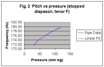
Robbing is the unpleasant effect caused by pipes going noticeably out of tune when they cannot draw sufficient wind from the groove, and it is caused by the pallet throttling the wind when many stops are drawn. It is of interest to quantify this effect. Accurate measurements of fundamental frequency (pitch) were made of a stopped diapason pipe taken from an organ sounding tenor E (174.6 Hz) as the wind pressure was varied. The measurements were made with the foot hole plugging intact, partly because this is the usual way in which pipes are regulated and it was considered important to use a pipe in the condition that would be found in an organ. However a more compelling reason was that, with the plugging removed, the wind pressures became so small that it would have been impossible to measure them accurately. Frequency was measured to a precision of 0.1 Hz with a microphone connected to an electronic frequency meter, and wind pressure with a water manometer. Results are shown in Figure 2.
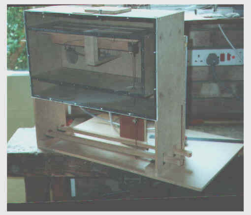
Between about 174 and 179 Hz the variation of frequency with pressure was accurately linear apart from measurement errors. Below this the pipe rapidly ceased to speak, and above it the pipe began to change to an overblowing mode in which it eventually spoke the twelfth. Such a characteristic is qualitatively in good agreement with the accepted theory of flue pipes 4, but it was necessary to do this experiment to get the accurate data needed for this work. The important point is that the pitch of a flue pipe will vary with any change in wind pressure, but it is clearly impossible to design a practical pallet that would not have any effect at all on pressure as the wind demand on it was varied by drawing different numbers of stops. So the question we have to answer is: what is the maximum amount of pitch deviation that would be acceptable for there to be a verdict of no robbing on an instrument? The empirical equation of the straight line was: f = 0.0829p + 170.2 (2) where f is fundamental frequency in Hz and p is wind pressure in mm wg. A pitch change that can be considered tolerable would be that which characterises a recently tuned organ, and a criterion of 0.2 Hz is suggested. This is the same as one beat in 5 seconds between two unison ranks of notionally the same pitch. So, using equation 2, a pitch change of 0.2 Hz would correspond to a pressure change of 2.4 mm for this pipe. At a typical working pressure of 75 mm this implies that the pressure in the groove should not deviate by more than about 3% when all stops are drawn. This sounded rather a tall order, and bearing in mind that the pitches of other ranks would also be shifting in the same direction (although not by identical amounts), perhaps a less demanding criterion of 10% would be a more reasonable figure to adopt for the regulation of wind pressure in the groove. For the pipe considered this would result in a pitch change of about 0.6 Hz. The beats resulting from such a deviation from true pitch would of course be highly noticeable, although perhaps not positively objectionable, so the 10% figure should be taken as an upper working limit for pressure regulation in the groove beyond which we should not go. Desirably we should aim for less than 10%. There are two distinct apertures associated with a pallet. One is the windway (a1) defined by the amount the pallet descends, and the other is the physical aperture closed by the pallet when at rest (a2). Values for the geometric areas of these apertures are given by: a1 = d(l + w) (3) and a2 = lw (4) where d is the pallet descent measured at the end of the aperture; l is the length of the pallet aperture; and w is the width of the pallet aperture. Superficially, a2 must not be less than a1 if the pallet is not to be throttled by its own aperture. But nor must it be too much greater if pluck is to be minimised, and this has been explored by John Norman 3 . From geometrical considerations he showed that nothing is gained in terms of air flow by making w > 2d, but for minimum pluck at the key w should not exceed 1.3d. This design rule was investigated experimentally. A test rig was built, illustrated below, in which a large pallet was used with a physical aperture (i.e. a2 ) 300mm by 18mm. However, constrictor plates could be fitted to the aperture to reduce it to any desired degree. Pallet descent could be set to any value, thereby varying a1, as could the wind pressure (up to a maximum of 300mm wg). The pallet fed a rectangular exit or load aperture situated above the groove (equivalent to the pipework fed by the pallet) whose area was variable by means of a sliding shutter. Two manometers monitored the input and output pressures at the pallet.
The pallet test rig This comprises two pallets, one of which is operated directly by means of a pull-down wire whereas the other incorporates various methods of touch relief such as a balanced valve. The latter are not described here but in another article on this site (see Touch Relief in Mechanical Actions). The rig was also used for experiments on electric actions, again not described here (see Response Speed of Electric Actions). Wind at about 300mm (12 inches) water gauge enters at the rear via a box fitted with an adjustable spill valve which enables the pressure to be set and automatically maintained at the desired level. The two water manometers referred to in the text are also at the rear, connected by PVC tubing to the input and output of the pallet. The sliding shutter which acts as a variable load aperture can be seen on the top of the box. The front of the box is covered with perspex (lucite). In the first experiment the effect of pallet aperture width (w) was investigated. Pallet descent (d) was constant at 6mm, and the input wind pressure was 100mm wg. Two values of w were used, 10mm and 18mm, the former value being obtained by using a constrictor plate over the pallet aperture. For each value of w the variation of output wind pressure from the pallet as a function of load aperture area was measured. Results are in Table 2.
Table 2. Variation of pallet output pressure as a function of load aperture and pallet aperture width (w). Input pressure=100mm; pallet descent (d)=6mm. One would of course expect to see the output pressure from the pallet falling as the load aperture increased in size. However the centre column shows that the rate of fall was greater for the narrower pallet aperture. Thus the narrower pallet exerted a distinct self-throttling effect as the load aperture was increased, compared to the right hand column which relates to a much wider pallet aperture. This implies that even a w/d ratio of 1.7 may be too small, thus the ratio of 1.3 suggested for minimum pluck would significantly worsen air flow. In a second experiment the pallet descent (d) was varied while keeping the aperture width constant - the full width of 18mm was used throughout. Two values of pallet descent were used (8 and 10mm), and the input wind pressure was constant at 75mm. For each value of pallet descent the variation of output wind pressure as a function of load aperture area was measured as before, giving the results in Table 3. The interesting feature of these results is that, while the windway of the pallet (a1) increased by 25% as the pallet descent increased from 8mm to 10mm, hardly any more wind was admitted by it. This can be seen from the centre and right hand columns - any differences between the two were small and dominated by experimental error, thus the pallet began to limit the delivery of air in both cases once the load aperture reached an area of about 500 mm2. Again, therefore, the w/d ratio of 1.8 was too small.
Table 3. Variation of pallet output pressure as a function of load aperture and pallet descent (d). Input pressure=75mm; pallet aperture width (w)=18mm. Therefore from these two experiments it seems desirable that the ratio w/d should exceed 1.8, particularly for pallets in which the descent d is large, and a value of at least 2 is probably more appropriate. Pluck will increase in proportion but this is inevitable. (Note that this conclusion is not incompatible with John Norman’s work, which concluded that in practice pallet aperture width could take values up to twice the pallet descent). The above experiments were necessary to ensure that subsequent work used a pallet that was not self-throttling, in view of the fact that robbing was to be investigated. The central question to be answered was: what size of pallet (defined in terms of its windway a1) is required to feed a given load aperture whilst maintaining the pressure drop across the pallet less than 10%? (Recall that the 10% criterion was derived from the earlier study on robbing).
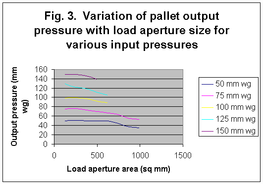
A series of measurements was performed with a pallet descent of 6mm and a generous aperture width of 18mm. Thus the pallet was unlikely to be self-throttled by virtue of the results just discussed. As before, the output pressure from the pallet was measured as a function of exit (load) aperture area for a given input pressure. This was repeated for a range of input pressures from 50 to 150 mm wg. Results are in Figure 3. For each curve, the load aperture which caused a pressure drop across the pallet of 10% was measured, giving the results in Table 4 .
Table 4. Load apertures resulting in a 10% pressure drop across the pallet for various input pressures. Pallet descent = 6mm; pallet aperture width = 18mm. There is evidence of a trend in the data, suggesting that the permissible load aperture gets smaller as the wind pressure goes up (apart from the value for 150mm pressure, which may have been unduly affected by measurement errors). However the decrease in load aperture values is only about 30% for a 3-fold increase in wind pressure, suggesting that we can average the load aperture values to arrive at an approximate single figure. This turns out to be about 600 mm2 . Since the geometrical pallet windway (a1) was about 1800 mm2 using equation (1), we can conclude that this pallet can only feed a load aperture one third of its own windway if the pressure drop across the pallet is to be kept below 10%. To see whether the result applied to other values of pallet descent, a number of other measurements were made. For example, for a descent of 8 mm (a1 = 2400 mm2 approximately) the load aperture for a 10% pressure drop was 750 mm2 , some 31% of the pallet windway. So, again, the factor of about one third applied in this case. The one-third factor is an important result for three reasons: the pallet dimensions and its descent used for the measurements are representative of what might be used for the lowest notes of an organ; the result was robust over a wide range of wind pressures and various values of pallet descent; and the easily measurable geometrical windway area a1 was used rather than vaguer parameters such as "effective aperture" or similar terms found in other work. Finally, we should recall that the work on robbing suggested that a pressure drop across the pallet of 10% was a working maximum and better should aimed for. So a more cautious approach would be to use a factor of between three and four for the aperture ratio to further reduce the danger of robbing.
We now have all the information necessary to design the pallets for the hypothetical organ represented by Table 1. Only the lowest 19 notes are considered here for reasons mentioned later. The following factors were used in designing the pallets:
Results are in Table 5. This table contains all parameters necessary to define a pallet for each note, and in addition it shows what the pluck at the key would be (assuming a key fall of 10mm and a wind pressure of 75 mm wg).
Table 5. Pallet design figures for the load apertures in Table 1. Some features of interest are:
Obviously, the numbers in Table 5 resulted from the particular set of load apertures used as well as the pallet design process itself, and they do not apply to any particular organ. Nevertheless the features discussed above and the sizes of the pallets themselves are not unreasonable; they are similar to those found in several successful mechanical action instruments. For example electric or pneumatic helpers (e.g. balanciers) are frequently fitted to the lowest two octaves or so, and multiple pallets may appear in the bottom octave. This confirms in a qualitative sense that the design process outlined in this paper is reasonable, including the generic load apertures in Table 1 relating to a hypothetical organ.
An experimental study from first principles has covered the main aspects of pallet design, including the air load presented by pipework, robbing, and the design of pallets which should avoid robbing. The following were the main results:
It is legitimate to ask whether the work described here advances or merely confirms the state of the art of pallet design, or even whether it contributes anything original. It is left to readers to make this judgement, but the fact that it is based entirely on simple ab initio measurements may make it worth having read this far. Because unsatisfactory organs (especially those with mechanical action) can still appear, as noted in the introduction to this paper, the degree of understanding of the subject clearly varies somewhat between builders. Hopefully the data herein will result in some clarification of the issues.
|