


|
|
|
TOUCH RELIEF IN MECHANICAL ACTIONS
by Colin Pykett
Posted: 5 November 2001 Last revised: 18 December 2009 Copyright © C E Pykett
Abstract. This paper summarises a recent experimental and theoretical study which looked at pluck compensation and inertial effects in large mechanical action organs using high wind pressures. A novel yet simple form of compensator was devised which (as an example) reduced the pluck of a large pallet from 335 gm to 90 gm at a wind pressure of 115 mm w.g. while allowing the player to retain direct mechanical control over pallet movement. Theoretical studies are also reported which estimate the maximum allowable length of tracker runs for a given repetition performance (e.g. 6 notes per second).
Contents (click on the headings below to access the desired section)
It seems from some examples of new organs with mechanical action that the requirement for a light and responsive touch is sometimes found to be incompatible with wind pressures high enough to generate adequate volume and presence in the building. Therefore a look at some of the problems was undertaken. The starting point was that no "cheating" was allowed; in other words, electrical assistance was definitely out, together with complex and expensive pneumatics such as floating levers. Only methods which maintained a direct connection between key and pallet were included, and the simpler the better. Two main problems were addressed: pluck compensation, and repetition capability. Let us begin with the pallet for the bottom few notes of a medium to large organ. The maximum amount by which the pallet descends cannot realistically be more than about 9mm (i.e. about the same as the key dip). For the pallet to be efficient the width of the aperture it covers should not be greater than about twice this amount, say 18mm. If it is wider the pallet will only amplify pluck rather than deliver more wind. The pallet can be arbitrarily long in principle, but a reasonable practical value is a 300mm long aperture. Such a pallet has a windway of about 2800mm2 although large instruments may need two or more such pallets for each of the lowest notes. (For a detailed treatise on pallet design see reference [1]). Let us assume a fairly high wind pressure of 115mm water gauge (w.g.). For the above pallet the pluck at the pull-down will be 337 gm, assuming this is in line with the end of the aperture remote from the hinge, and neglecting the spring tension. Because we are considering an action in which the mechanical advantage is unity (the pallet and key fall by the same amount), at least for this note, this is also the amount of pluck that the player would experience. It is obviously unacceptably large. What methods are available to reduce the playing weight of the action? Because we have restricted ourselves to looking at purely mechanical systems for relieving the touch, there are many variations but on relatively few themes. The Victorians made a variety of relief pallets, summarised in reference [2], which relied on a small pallet opening first in an attempt to equalise the pressures in the wind chest and the groove before the main pallet opened. This thinking was largely frustrated because the flow resistance imposed by the small pallet prevented much equalisation occurring when many stops were drawn. Also the relief which was obtained was not enough in relation to the pluck from pallets which were often too wide. There was also the idea of compensating the air pressure on the main pallet by a second contrivance such as a motor pulling in the opposite direction, as illustrated in Figure 1.
Consider first the case in which the dotted tubing connecting the motor to the groove is absent, thus it exhausts into the atmosphere. Clearly the motor exerts a pull in the opposite direction to that of the pallet in proportion to its surface area. Despite the claims made for it in certain literature (e.g. reference [3] where its operation was completely misjudged), it would generally be unable to relieve the touch as much as might be desired because if the motor pulls with a force greater than the spring, the pallet will not close again once it has opened. Unfortunately, pluck will often be greater than spring tension. Because ideas such as this could not possibly have worked as described, it makes one wonder how many of them were actually tried before their inventors rushed to the Patent Office. But if the tubing shown dotted is included, the device becomes the balancier (balancer) type of helper often used today. By allowing the motor to exhaust into the groove rather than the atmosphere, it experiences exactly the same varying pressure differences during key fall as does the pallet itself. Therefore there is no danger of over–compensation as with the previous scheme, and the helper motor can be made nearly as large as the pallet aperture in surface area so that the pluck can be almost completely cancelled if desired. One criticism sometimes voiced of this apparently admirable scheme is a degraded repetition capability (e.g. reference [4]), caused by an addition to the total inertia of the action owing to the mass of the motor components (comparable to an extra pallet) and the need to push air around. Although elaborations have been made, such as allowing the motor to re-inflate once the pallet has opened, the attractive simplicity of the technique then begins to be obscured by the additional complication. There would also seem to be another downside to the pneumatic helper technique because it does not fail safe. If any leakage were to occur through the motor the pipes might whimper, and the necessary soundboard repairs could be expensive. However a virtue can be made of this potential problem by deliberately arranging things so that the helper not only relieves the touch, but also assists in delivering wind to the groove. This can be done by making the helper a second pallet rather than a motor, as in the balanced valve familiar in fluid engineering. Usually the realisation of such a valve is not straightforward because it is difficult to make it shut off completely when closed, but in organs the compliance of the valve seating materials makes things somewhat less critical. Balanced valves were first introduced into steam engines, and the idea was considered by some organ builders including Hill (see, for example, references [5] and [6]). However it is not clear whether they were applied successfully. The difficulties are more of a practical nature than of the principle itself, such as realising a design which can be built and adjusted easily as well as ensuring the valve shuts off properly. This paper addresses these difficulties by describing an experimental investigation of the balanced valve principle. A practical realisation of a balanced valve is illustrated in Figures 2 and 3 in which the second "pallet" is depicted as a disc valve rather than a copy of the ordinary pallet itself.
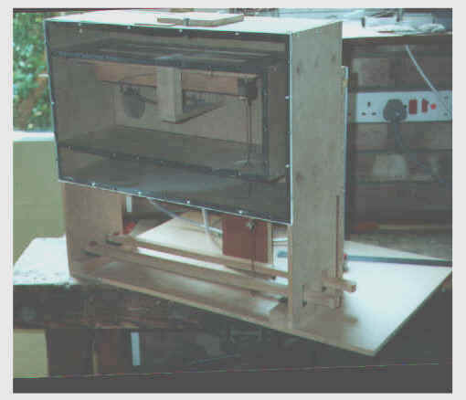
The area of the disc valve aperture is arranged to be somewhat smaller than that of the pallet, so that a reasonable amount of residual pluck is imparted to the touch. The disc-valve-plus-pallet unit must move as one with no lost motion, and the means to achieve this are of the utmost importance. Any "give" would result in ciphering, the classical problem of the balanced valve. Hence the suggestion of a disc valve rather than a conventional second pallet, as it is easier to gang the combination rigidly together. Another difficulty is that the final adjustment of the valve and pallet positions can only be done once the organ is in wind, as only then will the pallets and valves take up their fully closed positions against the compliance of the leather and felt. Thus means must be found to make this adjustment from outside the chest. But in theory a further advantage of the system is that a smaller main pallet can be used because the disc valve also supplies wind to the groove, provided that the connection is via tubing of substantial diameter. In turn, this means that the pluck to be compensated is also less to start with than in other systems. Also the system is extremely simple and implementations can be realised in which the valves can be readily adjusted without dismantling, as described below. Because the system was so beguilingly attractive in its simplicity, these issues were investigated experimentally. A test rig was built, illustrated below. The arrangement illustrated in the diagrams was used, in which adjustment of the valve separations was done merely by rotating the pull-down wire from outside the chest by turning the hook which connected it to the action. At one extreme the main pallet begins to open, and at the other the disc valve. Between these lies the optimum adjustment.
The pallet test rig
The main pallet was of the size already discussed with a 300 mm by 18 mm aperture. The disc was not, in fact, rigidly locked to the wire; it was allowed to just float slightly between two buttons to improve its seating. The experiments verified that the technique worked as intended up to wind pressures as high as 300mm (the maximum that could be raised in my workshop), and the experience gained threw up several design issues, particularly concerning the precise form of the disc valve. After many trials it was concluded that a conical valve was probably more effective than a disc in view of the greater seating pressure it conferred. This meant that the cone was drawn further against the compliance of the leather than a disc for a given value of residual pluck, with consequential sealing benefits. The criticality of the valve separations was investigated, as well as the practical effectiveness of the method of adjustment by rotating the pull-down. No particular problems due to wind leakage were encountered, because the compliance of the soft valve and pallet coverings was an advantage when adjusting for the optimum separation. Nevertheless to forestall doubt whether this would continue to be the case over long periods of time, a simple modification was also tried in which the conical valve exhausted into the atmosphere rather than into the groove. To reduce wind spillage to a low level this was done via a small hole. The diameter of the hole was not particularly critical because the absolute value of pressure on the conical valve becomes irrelevant once the pluck at the main pallet has been broken. It is only necessary that there is no pressure difference across it. The use of an exhaust hole leads to pressures on both sides of the valve equal to that in the chest while the pallet remains open. Note that this is different to the conventional balancier, which (as we have seen) will not work if it exhausts into the atmosphere rather than into the groove. Perhaps the main practical disadvantage of the scheme is that the conical valve diameter might be inconveniently large compared to the bar separations – with the pallet used in the experiments, a 50mm diameter hole was required for the valve to give a net pluck of 90 gm with a wind pressure of 115mm. (Without compensation the pluck would have been 337 gm). However we are speaking here of the lowest notes of a large organ so this might not always be a problem, but in any case both the pallet and conical valve apertures will reduce above the bottom note. Above a certain point, of course, no pluck compensation will be required - typically only the lowest 24 notes or so will require compensation. (An expanded discussion of these issues now appears in a review article elsewhere on this website [9]) Another problem of mechanical actions concerns inertia – critics say they are not sufficiently snappy because the force available to accelerate the action at key release is so small, an argument constructed forcefully by one concert organist in reference [7]. Putting some figures into this argument, assume that a minimum repetition capability of 6 per second is required (i.e. 6 repetitions of the same key). This means that the key, when released, must return to its normal position in at least one twelfth of a second solely under the influence of a spring tension of, say, 75 gm measured at the key. For a given key travel, elementary mechanics enables the necessary acceleration of the action to be calculated. In turn this enables a value for the equivalent dynamic mass (EDM) of the action to be obtained, from the ratio of spring force divided by acceleration. EDM is not the same as the sum of the actual masses in the action, and it is useful to understand how it is made up because the means for achieving a rapid key response lies in minimising EDM intelligently. The components of the action usually fall into three categories which are, in increasing order of importance:
(This ranking applies to actions in which the key is balanced or centre-hung, actuating a sticker at the rear. For suspended actions where the keys are longer and back-hung, it may not be appropriate). Therefore minimising EDM means, most importantly, achieving minimum tracker mass. To see how tracker mass affects repetition a mathematical model of the action is necessary, of which the details would be inappropriate here. Assuming typical values for the dimensions of key, backfall, roller and pallet, and assuming the usual materials, it can be shown that the maximum allowable total mass for the tracker runs is typically about 185 gm if a 6 note per second response is required. (The pallet dimensions inserted into the model were those used throughout this paper). With a typical hardwood tracker having a cross section 10 mm by 3 mm, this is equivalent to a total run of about 9 metres. This figure gives a reasonable degree of design flexibility even for large organs. However, increasing the repetition requirement to 8 per second results in the maximum tracker length decreasing to 3.5 metres, a reduction of over 60% for a decrease of only 25% in the repetition period. This example shows how strongly the tracker masses in the action influence its repetition capability. An analysis of the demands set by organ music for repetition capability appears in reference [8]. The need for an action to respond 8 times per second at the bottom end of the keyboard is probably excessive and the 6 per second criterion is therefore more reasonable, although higher in the compass it might be too slow. Consequently, except in the most difficult circumstances the figures above suggest that relatively large organs can remain responsive, but only if meticulously engineered and designed. For example, extreme attention needs to be paid to minimising tracker mass and consequently the use of hardwood and over-large cross-sections might be unwise where runs are long. Note that the analysis above did not include the inertial effects of pluck compensation devices. A balancier would usually have an effect that could not be ignored, whereas the minimal additional mass of a balanced valve would be negligible. 1. "Calculating Pallet Size", C E Pykett 2001, currently on this website (read). 2. "The Making of the Victorian Organ", Nicholas Thistlethwaite, chapter 11, Cambridge 1990. 3. "The Art of Organ Building", G A Audsley, vol. II figure CLXXVI, Dover 1965. 4. "Manual Coupling in Larger Organs", K Jones, Organists' Review, November 1999, p. 322 5. G F & J Stidolph patent (1860), outlined by B B Edmonds in BIOS Reporter vol XXV (4), October 2001. 6. "Musical Instruments in the Great Exhibition of 1851", W Pole, p. 64 (reproduced in Thistlethwaite [2], p.512). 7. "In the Pipeline", Carlo Curley, chapter 12, Harper Collins 1998. 8. "Response Speed of Electric Actions", C E Pykett 2001, currently on this website (read). 9. "The Physics of Organ Actions", C E Pykett 2003, currently on this website (read). |