


|
|
|
Console-building hints and tips
Colin Pykett
Posted: 6 May 2019 Revised: 8 May 2019 Copyright © C E Pykett 2019
Abstract. A consistently popular article on this site gives constructional details for a simple organ console. However it only describes the console shell rather than the furniture which it hosts such as keyboards, pedal boards, key contacts, pistons, stop controls and swell pedals. Therefore this article fills the gap by bringing together a collection of hints and tips relating to these items gleaned from my experiences in making a number of consoles. The emphasis is on ways to keep costs down without compromising too much on quality, and not at all on reliability, since purchasing new items is extremely expensive and not cost-effective for many people compared with the other approaches discussed here. Many of the suggestions in the article have survived the test of time over many years.
Contents
Using reed organ keyboards
Reed and optical switches
Types of pedal board
Multiway connectors versus pedal jacks
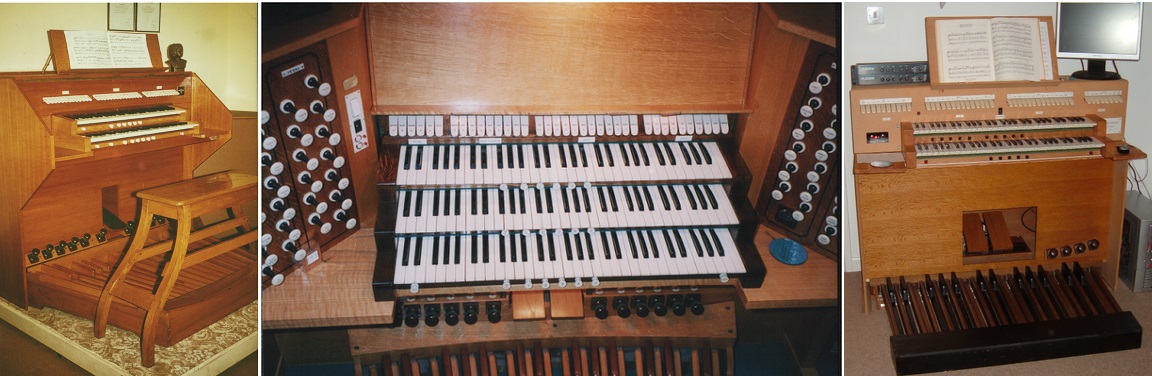
When posting a new article I never quite know what visitors to the site will find interesting, but a previous one on making an organ console quickly became popular [1] and some years on it still ranks consistently among the most frequently viewed pages. It described a simple console or keydesk for a virtual pipe organ (VPO), though it is of course suitable for any other sort. However it only described how to make a bench and the console shell itself, whereas items such as keyboards, pedal boards, key contacts, stop controls, pistons and swell pedals are also important. So this article draws together some practical hints and tips relating to console furniture gleaned from my experiences over many years in designing and making a number of consoles, three of which are shown in Figure 1. The right hand photo is of a fully populated console built around the simple shell mentioned above [1]. However, unlike the other two, it is not completely finished cosmetically as it was put together mainly for experimental purposes some years ago when the Prog Organ virtual pipe organ system was under development.
Figure 1. Consoles made by the author
The emphasis in this article is on ways to keep the costs of console furniture down without compromising too much on quality, and not at all on reliability, since purchasing most of these items from suppliers to the organ trade is astronomically expensive and simply not cost-effective compared with other approaches. This can lead to some bizarre consequences. For instance, if you want a complete console it could well be cheaper to buy it in the shape of a digital organ from a number of manufacturers rather than trying to make one up from standard pipe organ trade parts. They can keep costs down by virtue of their production volumes. Even if you did not like the sounds of the instrument you could use the MIDI signals which most digital organs generate to control your own synthesiser system such as a
VPO. Naturally, the cost saving would be still greater if the instrument were to be purchased second hand.
Satisfaction cannot be obtained from poor keyboards and they are impossible to construct, so you have to acquire them ready-made. At the top end of the cost spectrum are new ones from pipe organ trade suppliers as mentioned above, but these are extremely expensive especially when fitted out with springs and contacts. They will not be discussed further here, though if you decide to go this way it is unlikely that you will be disappointed with the playing experience. However pre-owned keyboards of similar quality appear from time to time on auction websites and they are eagerly sought after by knowledgeable bidders. Naturally, a certain amount of careful renovation will usually be called for but this is a small price to pay for quality items. High end examples of those which are sometimes advertised in the UK include the keyboards formerly used in Compton pipe organs and their Electrone analogue instruments. As of 2019 these will typically be around 60 years old nowadays, and made by the now defunct firm of Herrburger Brooks. They will usually be complete with Compton's proprietary silver wire contact blocks, plus thumb pistons as well in some cases. Keyboards of similar quality were also used by other makers of analogue organs from this era in the UK, Norwich Organs being one such. Somewhat lower down the scale of excellence but still worth considering were the consoles of other bygone firms such as Livingston Organs. They often incorporated wood core keyboards of reasonable quality, and again they might come complete with contacts. I got a pair of these, in which the pipe organ grade contact blocks used gold wire, for just £40 some years ago. They also were by Brooks, albeit their cheaper range, and they can be seen in the right hand photo of Figure 1. The thumb pistons in this picture were fitted subsequently and pistons are discussed later in the article. Although bidding wars on the auction sites might appear frenetic at times, if you really want such items they can often be yours if you put in a realistic bid in the last few seconds of the auction even if you have to sit up in the small hours of the morning. This works because most people seem to want something for nothing rather than being prepared to pay a decent price for a decent article, therefore they give up when you call their bluff with a respectable bid at the last minute. So bid aggressively within your price cap, though you won't need me to tell you this. Another approach is to visit your local pipe organ builder or digital organ showroom to see what they might have lying around. I know more than one case where people got entire drawstop consoles this way at knock-down prices from various well known firms who just wanted to recover the floor space occupied by an item with little or no remaining profit value.
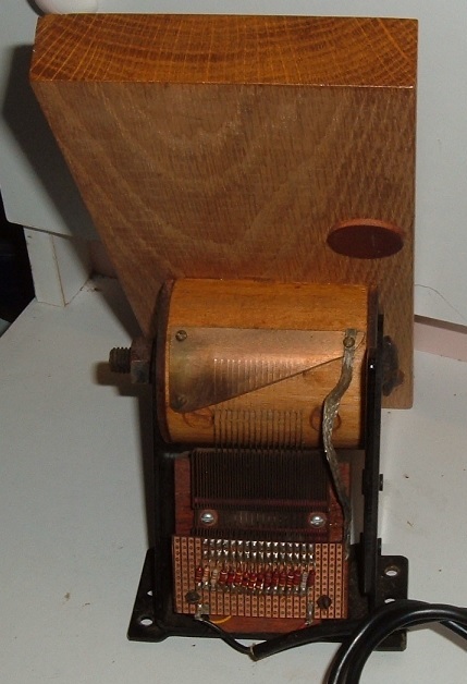
Reed organ keyboards are another possibility though they are seldom considered, which is odd in view of their quality. In the UK the instruments themselves usually attract little value and they often end their days in landfill, but I have cannibalised them for their keyboards in my time. Usually the wood cored keys are back hung on a removable frame with the naturals typically covered with a hard wearing celluloid-type material. This is attractive to the touch in a tactile sense, superior to modern plastics, and it polishes up well. Sharps are generally capped with ebony. So the keyboards are of good quality and worth considering. The modest cost can be offset even further by selling on the reed sets and other rare components to reed organ restorers, and this is satisfying from a recycling viewpoint. One problem is that most, though not all, reed organ keyboards have an F-compass whereas a C-compass is needed for pipe or digital organs. C-compass keyboards are found most often in positive pressure instruments (European harmoniums) rather than suction-operated ones (American organs), but it is not particularly difficult to make a new or modified keyframe complete with end cheeks and then re-pin an F-compass keyboard to suit the new layout. Basically all you have to do is move the seven lowest keys up to the top end. Using a pillar drill and the old keyframe as a pattern, the new pin holes can be positioned accurately.
Using commercial MIDI keyboards
Wood core keys of the general type just discussed are used in pipe and digital organs of the highest quality. Much lower down the scale of cost and quality are those used in commercial MIDI keyboards which target the pop music market. These use moulded hollow plastic keys mounted in a plastic case which only generate MIDI signals rather than emitting sounds of their own, but for many purposes (including VPOs) a MIDI output is exactly what is required. By removing the keys and electronics from the case the keyboard can then form one of a stack of several. However the touch of many such keyboards is disagreeable to an organist, so you need to find examples which are tolerable before purchasing them. I hesitate to recommend particular items, partly because those I have come across do not satisfy me in one way or another, but partly because my views are less important to you than your own. Having said that, the M-Audio Keystation 61 keyboards have a good reputation and they have been used by several suppliers to make up low cost keysets for virtual pipe organs (see references [2] and [3] for examples). However bear in mind that this product has undergone several evolutions over its lifetime, and the current version in 2019 is believed to be designated Mk III. Some of the design changes have been major, such as differences in overall width, so you will need to ensure that each one in your stack is of exactly the same type. As with pianos and reed organs, modern plastic keyboards sometimes have vertical fronts. They are also sometimes weighted to simulate a piano touch, which is not ideal for organ purposes. Another downside is that the keyboards might need setting up each time they are switched on, for example to prevent them generating the velocity-sensitive MIDI codes used for simulating pianos. Otherwise this might confuse some organ software which expects to see the same velocity value encoded within each Note On message. It is also quite possible that a keyboard will always transmit on MIDI channel number one when powered up, whereas organ software usually requires a different channel to be assigned to each manual. I have even come across keyboards which do not initially transmit in the correct octave since their default power-up state assigns a MIDI note number of zero (rather than the usual value of 36) to the lowest key. Some organ software might be configurable to compensate for these problems, but if not, it is inconvenient to have to keep punching sundry push buttons for each keyboard every time you switch your organ on. So it is highly desirable to use items which can remember their most recent setup status. I do not know whether the latest M-Audio products incorporate this feature, but some commercial keyboards do not and I can assure you from personal experience that it is a decidedly unattractive attribute.
If your keyboards do not have key contacts then they can either be purchased or made from scratch. This section of the article does not describe how to make them but instead it focuses on some important details which are essential to get right. The same details also apply if you elect to purchase commercial contact assemblies.
Magnetically operated reed switches will seldom work reliably for manual (as opposed to pedal) keys because the depth of touch is not great enough compared with the distance over which hysteresis is dominant between magnet and reed. Adjustments are so critical that the system is virtually unworkable in that some notes might either remain on when the key is lifted, or conversely remain off when it is depressed. Optical keying is much better, in which a shutter attached to the key interrupts an infrared beam, and this system is sometimes offered as part of a complete MIDI encoder package. As well as providing good long term reliability, the system allows precise setting of the firing point at which the circuit is made and broken as the key rises and falls.
Traditional wire-and-wiper or
wire-and-busbar contacts, as used in pipe organs for over a century, can work well over long periods for digital ones provided some basic design and implementation guidance is heeded. Gold is the preferred material where low voltages and currents have to be switched, as in digital organs, because it is unreactive and the surfaces will therefore remain unoxidised indefinitely. But the solid material cannot be used for reasons besides cost because it is too soft to maintain much of a temper over time, thus gold wire cannot be made sufficiently springy. For this reason so-called gold contact wire is made from a core of springy material such as brass or phosphor bronze onto which a thin covering of gold is rolled, not plated. This results in an electrically fragile material however, as the slightest trace of sparking will penetrate the gold surface and render the contact less reliable. Therefore gold clad (sometimes called gold filled or rolled gold) wire can only be used for switching minute currents, no more than a few milliamps. Nor must there be a significant current surge when the switch closes, perhaps due to excessive input capacitance in the controlled circuit, as this also will be sufficient to degrade the contact over time. Nevertheless, gold clad wire should desirably be chosen when buying or making key contacts for digital organs.
Metal fatigue with wire contacts
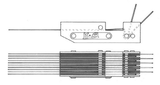
A number of mechanical as well as electrical matters have been discussed above. However there is a further mechanical factor which is important in contact design, namely the need to reduce the onset of fatigue failures in structures involving wires which are subjected to continuous bending strains. An important function of any key contact assembly is to isolate the brittle soldered connections from strain caused by the wire movement, otherwise frequent and early failure will result due to fatigue at the joints. So it is important to mechanically decouple the bending motion of the contact wire from its soldered connection, a point which should be taken into account if you make up your own contacts. A glance at the design of commercial contact blocks shows how this can be achieved (Figure 2). Whatever you do, don't just solder the contact wires to tags which expose the joints to the continual flexing of the wires as the keys move. They will, quite simply, always fail over time and eventually the wires will loosen or even drop off. Believe me, I know. I've been there in the days before I knew any better.
Figure 2. A key contact assembly showing a strain relief technique (image © Kimber Allen UK Ltd)
The electrical reliability of metal-to-metal contacts can be improved dramatically by including redundancy in the form of duplication. Thus, instead of using a single contact wire, a pair of contacts in parallel will improve performance significantly. Simple probability theory demonstrates this - consider a case in which a single wire-and-wiper contact has a one in four chance of failing on average, in other words it would have a 75% chance of working. This would be unacceptable for musical purposes because it implies that if you pressed a key four times in succession, on average you would get no response in one case. Yet by using two contacts wired in parallel instead of one the probability rises to nearly 95%. This means that a pair of unacceptably bad contacts will become nearly infallible when operated together. The reason is that the probability of both contacts randomly failing to conduct at the same time is much lower than that for each separately. The implication is that four wires instead of two should be considered for the usual wire-and-wiper configuration fitted to each key. Two of them are connected in parallel to the common supply and the remaining two connected to the keying circuit to be controlled.
Like manual keyboards, new pedal boards are expensive so the pre-owned market has to be looked at carefully, though fortunately they seem to appear quite frequently on internet auction sites. One reason for this might be that some people (or maybe their partners and families) find them ugly and difficult to accommodate in the average domestic setting once the initial excitement of a home organ has evaporated. However, unlike manual keyboards, it is possible to make them from scratch. Detailed instructions appeared in a book so old I would hesitate to mention it here were it not for the fact that it apparently remains widely available across the internet in 2019 [4]. Constructional details for a complete console can also be found there, which might be of interest in the context of this article. DIY constructional kits are also available from a number of sources (e.g. [5]) as well as some established trade suppliers.
The question of whether to go for 30 or 32 notes (or any other number) is up to you, though it is often answered by what happens to turn up while you are searching for a suitable pedal board. Almost no organ music demands 32 notes, and the main advantage of the slightly wider boards seems to be a cosmetic one in that they can be positioned more symmetrically in the console relative to the manuals. The narrower 30 note board has to be offset if the conventional criterion is adopted whereby middle D of the manuals lies vertically above the central D key on the pedals, and the resulting visual appearance seems to offend some people.
The subject of pedal key springing deserves a few words. There are basically two methods - heel springs and toe springs. Heel springs consist of tempered steel strips or plates to which the pedal keys are anchored at their rear ends, the other ends of the strips then being screwed to the heel end of the frame. Often, a laminated stack of several spring plates is necessary to get a sufficient return force for the key. An issue here is one of leverage in that the plates have to be heavily tensioned by screwing (and thus bending) them down hard enough to provide a sufficient weight of touch to the keys at their front (toe) ends. Even so, it can still result in a pedal board with a too light and 'bouncy' touch for some organists. This does not apply to toe springs, which are simply large versions of manual key springs mounted under the front ends of the keys, and it is easier to obtain a firmer (heavier) touch using these.
Most of what was written about manual key contacts above also applies to those for the pedals. However reed switches work better for the pedals since the depth of touch is much greater than for manual keys, meaning that the magnets can travel comfortably beyond the range of reed-magnet
hysteresis. But this only applies if they are fitted to the front (toe) ends of the keys rather than at some intermediate position where the key movement is smaller. However the reverse applies if traditional wire contacts are used, since it is not desirable to mount them at the toe end of the keys because they will be subjected to excessive bending which might cause permanent deformation over time or even complete failure. In this case it is safer to fit them onto a rail set back under the keys towards the heel end of the pedals where the effective depth of touch approximates to that of the manual keys.
Multiway connectors versus pedal jacks
The foregoing discussion assumed that the contact system, either in the form of wires-and-wipers, reed switches or whatever, is fitted to the pedal board itself. However this implies the need for a multiway connector on the end of a flexible cable to connect them into the keying circuitry of the organ. This will have to be carefully pulled apart each time the pedal board is removed from the console and plugged in again when it is replaced. Therefore an alternative approach is to fit the contacts, not to the board itself, but to so-called pedal jacks which are permanently mounted within the console. The jacks engage with the ends of the keys when the pedals are pushed into position and thus they operate the contacts. Their mechanical design in terms of leverage is such that the depth of touch of the pedals is reduced to match the requirements of the contact wires if this type of contact is employed. However this arrangement does not cope well with pedal boards which sink into carpets or where the floor is uneven, and in these cases the touch can become vaguely defined or upset altogether. Together with the additional complication and considerable extra cost, the upshot is that pedal jacks seem to offer few advantages today. They symbolise an old fashioned approach rooted in history when older pipe organs with an electromechanical action and analogue electronic organs both required many circuits to be controlled directly by each key. This led to numerous connections to the pedal contacts, more than could reasonably be accommodated in a detachable multiway connector. Nowadays, with the universal use of electronic keying for both pipe and digital organs, only a single pole switch is needed for each key. Together with diode matrixing, this means that a connector typically accommodating only twelve wires (capable of addressing an 8 by 4 contact array) is needed to connect a 32 note pedal board to the contact scanner. This is easily and reliably achieved within a single connector, but desirably a heavy duty one should be chosen to withstand occasional rough handling.
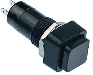
Like everything else associated with organs, the apparently simple thumb piston seems ridiculously expensive to purchase from trade suppliers for what it is, particularly as the contact arrangements in some of them are rudimentary and unreliable. Even the plastics of which some of them are made are cheap and nasty, leading to breakages in service which are by no means uncommon (e.g. the heads snap off). All this is frustrating since, when all is said and done, they are only push buttons. Of course, therein lies the answer to the conundrum. Suppliers to the organ trade have to sell at high cost into a conservative, small and specialist market whereas industrial push buttons of every conceivable variety occupy hundreds of pages in manufacturers' catalogues the world over and they sell in enormous production volumes. However this does not necessarily imply low quality, as the following will demonstrate.
Figure 3. Square push button suitable for use as a thumb piston
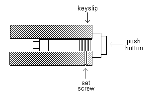
They can be seen fitted to the keyboards of the console shown in the right hand picture of Figure 1. In this case I discarded the nuts and washers provided and inserted the body of the push buttons into close-fitting holes bored with a pillar drill through the decorative wood keyslip and into the keybed behind so that the connecting wires could emerge from the rear (Figure 4). They were prevented from rotating by means of small brass countersunk woodscrews inserted gently from below. These had their sharp ends burred off smoothly to avoid damaging the button itself. Most of the pistons on this console are black but two red ones were fitted to the extremities of the lower keyboard to act as the combination capture setter button and a general cancel piston. An advantage of these buttons is that the diameter of the mounting hole is much less than that required for a barrel type of thumb piston, thereby inflicting less mutilation to the keybed and weakening it. This assumes particular importance when a large number of pistons are required. If your keyboards only have a thin vertical keyslip panel rather than one backed by the type of extended keybed discussed here, you can still fix the buttons easily by using the nuts and washers supplied. Therefore they are flexible in the sense of catering for different mounting options.
Figure 4. Mounting square push buttons in the keybed
The buttons cannot be obtained with engraved legends as far as I know, so this would have to be done separately at extra cost. However this also applies to the more conventional thumb pistons used by the organ trade.
The only topic to be considered relating to toe pistons or toe studs concerns the poor quality of the contacts found on some of them. This applies mainly to the older types used in pipe organs with an an electromechanical action in which contacts of the crudest form were often found, typically fabricated from a couple of pieces of bent phosphor bronze bridged by a base metal plunger. The whole assembly would oxidise rapidly. I well remember how pistons of this sort were unreliable in their day even when only called upon to operate relays, and they are of course completely useless for switching the digital signals in an electronic combination system. But there are still good reasons for considering such pistons today including the fact that they can often be obtained cheaply, they are mechanically robust against repeated assaults from the most enthusiastic foot-jabbing player, they look the part and they are entirely satisfactory from tactile and ergonomic points of view. All the consoles shown in Figure 1 used the same type of piston with a bronze-finished cast metal body which polishes up nicely, and I believe they were originally made by the long-lost firm of Ernest Holt of Walsall in England. But, as I said, the contacts are just awful.
Figure 5. Toe piston buffer circuit
This was developed originally to drive an electronic reverser module in a system with motorised (magnetically operated) drawstops and stop keys. Without this circuit the stop would typically shuttle on and off several times each time the piston was pressed owing to contact bounce, finally coming to rest in an unpredictable position. More bizarrely, the same sometimes happened when the piston was released. The circuit applies around 15 volts to the piston contacts, derived from the supply used to drive the magnet coils, but reduces it to 5 volts (or any other desired value) to suit the logic devices in the reverser or other target system. Because it uses a transistor amplifier together with the relatively high applied voltage, the high resistance of dirty or oxidised contacts is no longer an issue. The make and break transitions of the contact are also speeded up by the amplifier, and collectively these design features eliminate contact bounce for all practical purposes. The transistor can be any general purpose low power silicon PNP device. Originally I used a BC213 but this is now obsolescent and many cheaper components with comparable or better performance can now be obtained. Fitting the buffer circuit to each toe piston removes switching troubles to the extent that the contacts do not need cleaning at all. It has definitely turned out to be a fit-and-forget solution to the problem and one which has given trouble free service over several decades.
There are many possibilities for controlling organ stops, some extremely expensive and others very cheap. Among the latter are some possibilities for DIY construction. They will be discussed here under the headings of
drawstops, stop keys and touch screens.
Most of what has been said for drawstops also applies to stop keys. Thus there are several options ranging from expensive motorised tab or tilting tablet units, through the near-ubiquitous illuminated rockers to a number of DIY possibilities. The latter include commercial rocker switches supplying the electronics, automotive and mains power industries. A huge variety is available, though many will be too mechanically noisy for use in an organ. Instead of tabs, a row of illuminated push buttons (or buttons with separate lamps) can also be used in the same way as mentioned above when discussing
drawstops.
Conventional stop controls such as drawstops and stop keys offer no flexibility in labelling when multiple names have to be associated with each stop, as in VPOs with several sample sets. This was mentioned above where some solutions were discussed. Thus a widely used alternative is the use of touch screens on which some sort of representation of the stops being simulated is displayed. Although cost-effective, the disadvantages include complete loss of the tactile and ergonomic attractiveness of physical stop controls and, with some screens, only single touch operation is possible. Therefore the manipulation of more than one stop at a time which is possible with drawstops and stop keys is not possible in this case. The appearance of a console with touch screens instead of arrays of physical stop controls is also considered aesthetically unattractive by some. Thus touch screens imply a major sacrifice is made in terms of the traditional attributes of conventional stops which have to be given up in return for the single benefit of flexible stop labelling. However there is usually an overall cost advantage in addition, at least compared with motorised stop controls.
Only that type of swell pedal which generates MIDI codes for digital organs is considered here rather than attempting to cover the entire subject, since a more detailed discussion is available elsewhere on this website
[6].
Figure 6. A pipe organ electric action swell pedal wired as a potentiometer
1.
"A simple console for a virtual pipe
organ", an article on this website, C E Pykett 2013.
|