


|
|
|
Reversible pistons - or how the pipe organ predated the computer
Colin Pykett
" a book could be written about the many ingenious designs devised for this one piece of organ action" H Norman & H J Norman [1]
Posted: 4 December 2014 Revised:
21 December 2014
Abstract. This article discusses reversible piston mechanisms by showing that they all require a memory which holds the reverse of the current position (on or off) of the controlled stop. This stored information then reverses the position of the stop when the reverser piston is pressed. It is also shown that the complete system, comprising the controlled stop plus its internal mechanism, is a bistable device which is similar in terms of its logical design to the countless millions of bistables which make up today's electronic computers. Therefore in this sense the familiar reversible piston of the pipe organ which we take for granted predated the computer by at least a century.
In the earliest mechanical reversers the internal memory element was a wooden 'poppet', and the way this worked is described. Poppets continued to be used in pneumatic and electropneumatic reversers until well into the twentieth century, when they were displaced by fully electric systems using electromechanical relays. Several varieties of all these types of mechanism are described in detail. The article concludes by examining entirely electronic reverser systems having no moving parts and in which the internal memory is realised by a transistor bistable circuit akin to those used in computers.
Contents (click on the headings below to access the desired section)
Reversible pistons on an organ control single stops, such as couplers or solo stops, using the neat expedient of a double-acting approach - when the piston is first pushed it brings the stop into action and when it is pushed again it cancels it. Sometimes other functions which do not involve moving a stop in or out, such as 'Full Organ' or John Compton's former 'luminous touches', are also controlled in the same way. The piston can either be a button in a clavier keyslip, a toe stud or (less commonly nowadays) a projecting metal or wood pedal, or the luminous.stop head itself. Although the quotation above by Herbert and John Norman confirms the wide variety of mechanisms which have been devised to implement the reverser function, I am not aware of any concerted attempt to describe them in the literature. The only source I have found which comes anywhere near delving into the nuts and bolts of the matter is Noel Bonavia-Hunt's book of 1947 describing the British organ of his day [2], but even this is a brief (though nevertheless useful) survey occupying only a page or two. Hence this article, which takes the reader somewhat further though it makes no pretence to be a complete account.
It is unclear who first introduced the idea into organ building or when it first appeared. Elliston [3] credited 'Father' Henry Willis with inventing a reversible thumb piston, presumably operating a pneumatic action to control the drawstop and the associated mechanism. He certainly did invent thumb pistons, which he demonstrated in his organ at the Great Exhibition of 1851, but fully mechanical and possibly other pneumatic reverser embodiments almost certainly existed before that. Subsequently, electropneumatic and then fully electric variants appeared until reversers were finally incorporated into the electronic control systems we are familiar with today. Even these are not entirely universal however, as electromechanical reverser systems employing relays are still used occasionally, which explains why the necessary mechanisms are still (2014) available from organ supply houses. We shall therefore discuss examples of all these later, omitting only the most recent types which form part of a fully computerised organ control system and in which the reverser action itself is implemented in software rather than hardware.
We assume in this article that the controlled reversible drawstop or stopkey is motorised in that it physically moves in response to the reversible piston being pressed. This differs from a blind system in which the stops themselves do not move. That said, it is of interest to look at the the action of a reverser at the more formal level of binary logic devices. Regardless of how it is implemented, be it mechanical, pneumatic or electric, the essential push on/push off action is actually that of a bistable mechanism which can assume one of two stable states. In fact the controlled stop plus its internal mechanism constitute a binary counter which can assume the values 0 or 1 at its output, the output being the state or position of the stop itself. A binary counter therefore moves between 0 and 1 alternately in response to successive inputs in the form of successive prods of the reversible piston. Conceptually it is no different to the decimal count wheels found in gas and electricity meters, and in the odometers of older cars. Each wheel cycles round the digits 0 to 9 before returning to 0 again. But since a binary system is limited to 0's and 1's only, a binary counter can only cycle between 0 and 1. The internal mechanism of the reverser must also respond to (it must 'know about') the current state of the stop it controls because this can also be moved by hand independently of the reversible piston. This means the state of the bistable must be presettable. The internal mechanism must always store or memorise the opposite or binary complement of the visible state of the stop - if the stop is on (represented by binary 1, say, though the rather confusing opposite convention can also be used if desired) the internal mechanism must be at binary 0. Then, when the piston is pressed, it is this stored or memorised state which will cause the stop to go off. The act of releasing the piston then sets the internal mechanism to binary 1 in readiness for the next press, which will put the stop back on. But moving the stop by hand must preset (alter the state of) the internal mechanism by causing its stored state to change in readiness for the next piston press. And if there is a Cancel piston on the organ, this must clear the bistable by always setting the stop to its off position. In terms of binary logic devices, a 'presettable bistable with clear' element is exactly that used in its countless millions at the heart of all computers, thus we can say that the logical design of the reversible piston developed for the organ predated the electronic computer by at least a century.
Finally, means must be incorporated to prevent the system oscillating continuously while the piston remains depressed, at least with pneumatic or electric systems which can call on an essentially unlimited amount of external power. This instability problem would not affect a purely mechanical system operated by a foot pedal, say, even though it was improperly designed and would not work in other ways, because the system ceases to have access to power once the foot leaves the pedal. Many a naive designer will have come up with their first attempt in which the drawstop shuttles to and fro all the time, though I doubt most would be prepared to admit it! (I made this mistake while still at school, though fortunately I spotted the error of my ways before starting to build the system). An additional practical refinement is that a reverser must not cause the controlled stop to move unpredictably when the organ is switched on or off. It is annoying if a stop suddenly pops out when you turn the wind on, especially so if you do not notice it before starting to play! Thus it can be seen that reversible pistons are somewhat more complicated than they might appear at first sight, and this provided the motivation for writing the article.
The previous discussion showed that all forms of reverser, be they mechanical, pneumatic or electric, must incorporate some form of internal memory capable of storing a single binary digit (one bit). It was also explained that the binary state (0 or 1, off or on) stored in the memory must always be the opposite (the binary complement) of the current state of the stop, so that the stop will move to adopt this stored state at the next press of the piston. Here we explore some of the various types of mechanical, electromechanical and electronic memories which have been employed in reverser systems since their earliest days.
The earliest reverser systems were fully mechanical, operated by means of a projecting foot pedal above the pedal board, and in these the internal memory element was a poppet. Poppets continued in use when pneumatic and then electropneumatic reverser actions were introduced, and they only disappeared when fully electric systems using relays came onto the scene in the twentieth century. Thus we can illustrate the action of a poppet by looking at the pneumatic reverser action described in Bonavia-Hunt's book [2]. His diagram is reproduced here at Figure 1.
Figure 1. Pneumatic reversible piston using a poppet (after Bonavia-Hunt [2])
Quoting his description:
"The oldest form of reversible control was introduced in the form of a mechanical horseshoe pedal or 'poppet' which brought the great to pedal on and off alternately. Today reversibles are controlled either pneumatically or electrically by means of thumb or toe pistons. Figure 1 gives a diagram of the action of a pneumatic reversible piston action. The push of the piston head at the console releases pressure wind through the supply tube to the pneumatic motor X. The poppet (which shuffles to and fro on a centre-roller Y) is swung over to the right so as to engage the right hand pivot as shown. The guide arm is thus driven to the right and pushes the drawstop rod to the right by means of the metal connector. But as soon as the drawstop rod has moved out and the piston is released, the spring attached to the poppet forces the poppet to return to the status quo, so that the engaging point on the left will now contact the left pivot. The next time the piston is pushed the poppet will take the stop in. The stop is shown as drawn out in the drawing. This method works best with a short draw or with a stop key movement at the console."
It is a little difficult to understand fully how a poppet moves until one has the opportunity to see one in action, and Bonavia-Hunt's somewhat vague description and diagram might cause confusion. Nevertheless the general idea should be reasonably clear. By dispensing with the pneumatic motor and actuating the poppet instead from a connecting rod attached to a foot-operated pedal, we can visualise the essentials of the earliest mechanical reverser actions. Note that the poppet will swing over to the opposite position if the drawstop is moved by hand, thereby implementing the essential presetting function required of any reverser action. It can be seen that the mechanism consists of three essential items - the poppet (the memory), the stop actuator (which reads the stored state of the memory) and a spring connecting the two. These are present in all forms of poppet mechanism known to me even though the way they are implemented can differ.
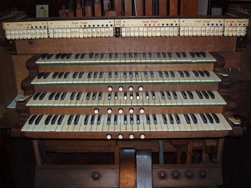
The next stage in the evolution of reverser actions was to operate the internal mechanism, the poppet, electropneumatically. This was a relatively small step beyond the pneumatic mechanism just described. We shall now examine a reversible stop which was implemented in the Hope-Jones organ at St Paul's, Burton upon Trent, built in the 1890s. The handsome detached console of this instrument is at Figure 2, and the picture is included to show the motorised tilting tablets used to control the speaking stops and the couplers. The console is in the care of the Lancastrian Theatre Organ Trust in Manchester, and it is on display in their museum devoted to Hope-Jones. The reversible piston controlled the great to pedal coupler which was the 8th tablet from the extreme left of the stop sweep [4].
Figure 2. St Paul's, Burton upon Trent (Hope-Jones, 1894) (Copyright © Lancastrian Theatre Organ Trust)
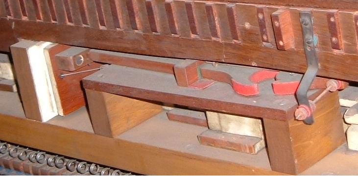
Figure 3 shows the mechanism at the rear of the console.
Figure 3. Electropneumatic reversible piston mechanism using a poppet at St Paul's, Burton upon Trent (Hope-Jones, 1894) (Copyright © Lancastrian Theatre Organ Trust)
Again the heart of the system was a poppet, and although its design was different in detail to that illustrated previously, the essentials remain similar. Both systems have a poppet and an actuator linked to the stop knob or stopkey, the two being connected by a springy wire. Here, the piston at the console closes an electrical circuit, energising an electromagnetically-controlled valve in a separate valve chest (not visible). The open valve passes pressure wind to the large pneumatic motor at the left of the picture, causing it to inflate. This pushes the poppet (shaped like a spanner or wrench) towards a pivoted swivel block (the actuator). One of the horns on the poppet engages with one of the notches on the swivel, causing it to rotate. The swivel is connected by a mechanical linkage to the appropriate wooden trace or drawbar, which in turn flips the stop tablet up or down at its far end. In turning, the swivel bends the spring wire which can just be discerned. Because the wire (now under strain) passes through an eye on the poppet, the latter swings into its alternative position when the piston is released and the pneumatic motor deflates. The deflating motor takes the poppet with it because the poppet is keyed into a pivot on the motor at its left hand end. Note that the wooden bridge block retaining the poppet is itself free to move laterally on the felt pad which can be seen. If the stop tablet is moved manually, the wire attached to the swivel block bends in the opposite direction, and this causes the poppet to swing into its alternative position.
I made a replica of this ingenious mechanism and found the precise shapes, dimensions and operating clearances of the moving parts to be rather critical if it was to function correctly. In the actual organ, the friction and inertia of the heavy mechanism also demanded that considerable force be applied to it, hence the substantial size of the pneumatic motor - the mechanism needs a really good shove before it will move the stop tablet. Both these issues make one wonder how reliable the system might have been in practice before adjustment or renovation were called for. Note that these remarks are not criticisms directed solely at Hope-Jones as they apply to any system fabricated from large wooden parts like this one. (If you doubt this, try making one yourself as I did!).
WARNING
Relay-based systems
The next evolutionary stage occurred when fully electric, as opposed to electropneumatic, actions arrived. Prior to that there was a major power supply problem because organ actions had to be designed to run on primary or secondary (rechargeable) batteries - by no means all organs could call on essentially unlimited power from dynamos or the street mains until the twentieth century was well advanced. Therefore electropneumatic actions held sway at first because these consumed relatively little power as the heavy work was done by pneumatic motors controlled by small electromagnets. In these systems much effort was also expended by builders such as Hope-Jones in developing ingenious power-saving circuits in which magnets not actually performing a function would cease to draw current from the batteries.
These awkward problems vanished at a stroke when sufficient prime power became available, and this led to actions in which electromechanical relays proliferated. Moreover, it no longer mattered whether the relay coils were energised for indefinite periods as power-saving schemes were no longer necessary. These changes resulted in relays appearing in fully electric reverser actions, and in particular the necessary 1-bit internal memory function was also realised using a relay instead of the former clumsy poppet.
Most if not all organ builders designed and made up their own reverser actions of this type before the second world war. However there was an unfortunate consequence. Despite the ready commercial availability of high quality relays which had long been developed for telegraph and then telephone systems, organ builders as a rule seemed to enjoy making up their own from odd bits and pieces which they presumably had lying around the workshop. Some of these home brewed relays were frankly bizarre and they were equally unreliable. As an example, relay movements involving bits of bent tinplate operating electrical contacts of the crudest nature proliferated. I have never been able to understand not only why this ever happened, but why this unfortunate phase of organ building lasted so long. Even today one can still find curiously non-standard relays sold at considerable cost when more reliable industry-standard items have long been available far more cheaply from electronic component suppliers. But no matter - I have to describe the scene as it was, like it or not.
One of these home brewed electric reversible piston systems from that pre-war era emerged from the Willis III firm, illustrated in Figure 4.
Figure 4. A fully electric reversible piston mechanism (Willis III c. 1930)
The picture is taken from Bonavia-Hunt's book alluded to already [2], and as before we shall again refer to his description of the device:
"Here the mechanism is shown ready to operate the 'on' solenoid of the drawstop (or the magnet of a stopkey unit). As soon as the reversible piston is pressed, the positive lead A (from the piston) will be charged. This operates the large electro-magnet B and at the same time charges the contact C which is resting on the contact at D. The latter is connected with the 'on' solenoid of the drawstop (or stopkey magnet). Thus the stop will be brought on. When the stop is on, the negative circuit at F is charged and the solenoid G tries to lift its armature, but is prevented from doing so by the energised magnet B. When the piston is released, the magnet B is no longer energised, and so the solenoid G is able to lift its armature and with it the contact C: the latter breaks with D and closes with E, thus preparing to withdraw the stop next time the piston is pressed."
Boanvia-Hunt neglected to mention that if the drawstop or stopkey is later moved by hand to the 'off' position, the armature drops and the system is then preset to respond correctly to the next depression of the piston - as required.
In my time I have played several Willis III organs of this vintage having this type of reversible piston mechanism (including one at King's College, London and another at St Andrew's, Kingsbury near Wembley). Provided the instrument in question had a detached console (both those mentioned did), it was always possible to tell whether this system was in use from the peculiar 'bouncing' noise which emanated from within when the floating armature dropped onto the lower contact under gravity!
Regardless of any other factors, such as reliability, it stretches credulity to understand how any organ builder could have undertaken so lightly the routine in-house manufacture of such items - which clearly involved much precision machining of wood if not metal - when it would have been far cheaper to send an apprentice out to the nearest electrical supplier to buy a pair of commercial relays to do the same job! One can only conclude that there must have been little commercial pressure to minimise labour and overhead costs in those days.
Many functionally similar devices have been made by organ builders or marketed within the organ trade for over half a century (at least since the 1960s if not before), and they have been used widely. One example which is still available (2014), though at considerable cost compared to a pair of industry-standard relays, is illustrated in Figure 5.
Figure 5. A currently-available (2014) fully electric reversible piston mechanism
Its operating principle is similar to that of the long-obsolete Willis system. The state of the stop is memorised by the lever arm magnet which moves to track its position, but this is prevented from moving by a second magnet which clamps the mechanism while the piston remains depressed. When the piston is released, the armature assembly moves to the correct position in readiness for the next piston press. A pair of changeover (single pole/double throw) contacts are operated by the armature extension. The circuit diagram of a reversible piston system incorporating this device is at Figure 6. The diodes are used only as spark suppressors and they play no role in the basic functioning of the circuit, which should be comprehensible if you have understood the previous description of the Willis system.
Figure 6. Reversible piston circuit using the electromechanical reverser unit of Figure 5
I have mentioned already that I cannot identify with the mindset which continues to use expensive custom devices like this in the organ building world. I guess we shall just have to agree to differ. Nevertheless, to demonstrate an electromechanical reverser using a pair of much cheaper industry-standard relays, one of many possible circuits is shown in Figure 7. I developed this many years ago and it has been used widely. As before, diodes are used for spark suppression but an additional one (that which feeds the resistor R) is part of the logic design in this case.
Figure 7. Electromechanical reverser using two industry-standard relays (C E Pykett)
Counter circuits, including reversers, sometimes seem at first sight to be more complex than they need to be, but this is because they have to be robust to what are called 'races'. In relay circuits races occur when two or more relays are changing state simultaneously, and during this period the behaviour of the circuit is undefined. If races are not controlled in some way the circuit will likely malfunction because its behaviour will usually depend on which of the contacts happens to close or open first, and often this is governed more by chance than design. When extreme operating speed is not an issue, as here, races can be controlled quite simply by slowing down the operation of the circuit so that events occur in a controlled and sequential manner. With a reverser, races will not occur if the circuit works faster than the stop unit itself. This is generally not difficult to arrange if the stop unit employs mechanical movement as with ordinary stopkeys or drawstops, because the time required for the stop to travel between its on and off states is significant.
In the circuit as drawn, RLY1 requires two sets of contacts, denoted 1a and 1b in the diagram, and RLY2 requires one set, denoted 2a. However the contacts 1b were included as an additional precaution against races and it will usually be possible to omit them, thereby making both relays identical and each with a single set of changeover contacts. The function of 1b is to ensure that the stop unit does not change state before RLY1 has done so, but since the relay will almost always be faster than the stop unit itself this should satisfy the race criterion automatically. RLY2 is the 'memory' relay which tracks the state of the stop, and RLY1 is the inhibitor relay which prevents RLY2 changing state as long as the piston remains pressed.
A resistor R is shown in series with the coil of RLY2 because the circuit was designed to operate at 15 volts whereas 12 volt relays were assumed. It is not really necessary to use a resistor for RLY1 in this case because it is only energised momentarily while a piston is pressed.
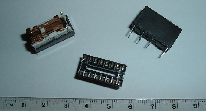
There is a wide range of relays which would be satisfactory for this application, some of them very small and costing well below £1 each. Using tiny BT47-style relays as shown in Figure 8 will result in virtually noiseless operation, although this will also be true of many other types today.
Figure 8. A BT47 style miniature relay with its plug-in holder
Before continuing please ensure you have read the WARNING further up this page.
It is possible to design a fully electronic analogue of the relay-based system just discussed, in fact there is almost no limit to the number of ways it can be done. The circuit of one example, again designed by myself, is shown in Figure 9.
Figure 9. An example of a fully electronic reverser (C E Pykett)
Those familiar with digital electronics will recognise that the two transistors on the right with their characteristic cross-coupled positive feedback loops form a bistable circuit, and it is this which implements the necessary 1-bit memory required of any reverser. In a bistable, only one of the transistors conducts at any one time, and in addition it completely shuts off the other one. This state will persist indefinitely until a voltage pulse arrives which reverses the state of the bistable by shutting the active transistor off and switching on the other. The transistors each control one of the magnet coils of the stopkey or drawstop unit. The remainder of the circuit deals with steering the pulse resulting from a piston press to the correct 'side' of the bistable, and with inhibiting this pulse from triggering the bistable until the piston is released. Operating the controlled stop by hand triggers the bistable directly so that it takes up the complement (reverse) of its previous state, in readiness for the next piston press. Because bistable circuits lie at the heart of all computers we see that the earliest mechanical reversible piston systems, which were also bistable mechanisms, did indeed predate computers by at least a century.
Further discussion of electronic reversers, including yet other circuits, can be found in another article on this website [5].
Although controlling organ stops by electronic hardware is a mightily large field in itself, the story does not end here. We shall not even begin to consider how microprocessor-based organ control systems work because here we enter yet another domain, that of software - computer programs in other words. So the quotation at the head of this article, that "a book could be written" about reversible pistons, is certainly true. Hopefully this article will have provided a flavour of what might be found in that book were it to appear.
This article introduced reversible piston mechanisms by demonstrating that they all require a 1-bit memory into which is written the binary complement (reverse) of the current on or off state of the controlled stop. It is this stored memory state which is then read out and which reverses the state of the stop when the reverser piston is pressed. It was also shown that the complete system, comprising the controlled stop plus its internal mechanism, is a presettable bistable device which is essentially identical in terms of its logical design to the countless millions of bistables which make up today's electronic computers. Therefore in this sense the familiar reversible piston of the pipe organ which we take for granted predated the computer by at least a century.
In the earliest mechanical reversers the internal memory element was a wooden 'poppet', and the way this worked was described. Poppets were also used in pneumatic and electropneumatic reversers until well into the twentieth century, when they began to be displaced by fully electric reversers using electromechanical relays. Several varieties of all these types of mechanism were described in detail. The article concluded by examining entirely electronic reverser systems having no moving parts and in which the internal memory is realised by a transistor bistable circuit..
1. "The Organ Today", Herbert Norman & H John Norman, Barrie & Rockliff, London, 1966
2. "The Modern British Organ", Noel A Bonavia-Hunt, Weekes, London, 1947
3. "Organs and Tuning", 3rd edition, Thomas Elliston, Weekes, London, 1898
4. It is possible that the great to pedal reversible piston at St Paul's, Burton upon Trent, was added subsequently by Norman and Beard at one or other rebuilds of this instrument in the 20th century after Hope-Jones himself had emigrated to America in 1903.
5. "The Evolution of Electric Actions", Appendix 1. An article on this website, C E Pykett, 2005
|