


|
|
|
Viscount Organs - some observations on physical modelling patent US7442869
Colin Pykett
Posted: 27 April 2016 Revised: 7 June 2016 Copyright © C E Pykett 2016
Abstract. This article discusses the patent on the physical modelling synthesis of organ flue pipes granted to Viscount International SpA. It is confined solely to the patent specification rather than speculating on technical aspects of Viscount products, which might differ. The modelling concept described in the patent departs from that usually discussed in the literature in that there is no coupling or feedback between the sound generating and resonating elements of the simulated pipe. Moreover, the generator model described in the patent does not correspond to the type of nonlinear oscillator normally assumed when modelling flue pipes and similar wind instruments. Instead it models the acoustic excitation signal applied to the resonator rather than modelling the oscillator itself for reasons which are described in the patent. On the other hand, the resonator is modelled according to generally accepted physical modelling principles relating to waveguide synthesis, and this makes the system unique to Viscount as far as digital organs are concerned. The model is rich in terms of the number of parameters which can be adjusted to achieve the sound desired. Virtually everything which can be adjusted seems to be software-adjustable, leading to a potentially wide range of voicing options. The article is offered to expand some technical aspects of an innovative and novel approach to digital music synthesis, and to make them more accessible to a wider and less specialist audience than that targeted by the patent itself.
Contents (click on the headings below to access the desired section)
Flue pipe model as implemented by Viscount
Viscount International, the Italian musical instrument manufacturer, is currently the only firm offering digital organs using physical modelling synthesis. Most others rely on sampled sounds, though there are also a few which still use additive synthesis. More details about these techniques can be found in reference [1], but at the outset it is worth emphasising a cardinal point which separates physical modelling from other methods. Physical modelling models the instrument, whereas all other methods model its sounds. It is essential that you get your mind around this distinction because it sets it apart from all other pipeless organs ever made. A range of Viscount instruments using a physical modelling system called 'Physis' has been available in the UK since about 2009, but before that a smaller MIDI expander box (the CM-100) came onto the market around 2006. Still advertised at the time of writing (2016), this uses a physical modelling technique called 'Accupipe'.
Digital organs using the earlier techniques of sampled sound and additive synthesis were invented respectively by Allen Organs in the USA and Bradford University in the UK, in the sense that they patented the technologies and developed them to a level at which they could be brought to market. Because they have been available for a long time, some 45 years in the former case and 35 for the latter, these two synthesis techniques are broadly familiar to the digital organ community. However physical modelling is perhaps less well understood even though the method has been used widely in simulating other musical instruments for some years. Viscount was the first company to apply it commercially to simulating the pipe organ fairly recently, and it remains alone in the field in 2016. Therefore I decided to write this article to throw a little more light on the subject, drawing on a patent describing the approach adopted by Viscount which was invented by Carlo Zinato.
A United States patent describing their method of modelling organ flue pipes was filed in 2004 and granted in 2008 [2]. It has also been patented widely elsewhere. The patent specifications filed in different English-speaking countries appear to be the same, apart from some variations in their 'claims' sections. The reason for choosing the American version here is only because its paragraph formatting makes it somewhat easier to read. Therefore the patent is contemporaneous with the two product lines mentioned above. However it is not known how closely it describes details of the technologies which the firm actually uses because patents and their embodiments in products frequently differ, and furthermore the patent makes no mention of these products. This should be borne in mind while reading this article. Therefore, from now on the article addresses the patent itself rather than the commercial offerings. It seems reasonable to regard this patent as completing an important trilogy whose other members are the Allen patent of 1971 [3] and the Bradford patent of 1980 [4], since together they cover the genesis of the three main organ synthesis technologies in current use (the first two have long since expired of course, whereas that of Viscount is still in force at the time of writing).
I have no connection with Viscount or any of its associated companies. However, because they are the only manufacturer currently marketing organs using physical modelling synthesis, in fairness to them I wish to emphasise that nothing here is intended to disparage their products. The article is offered in good faith only to amplify some technical aspects of an innovative and novel approach to digital music synthesis, and to make them more accessible to a wider and less specialist audience than that targeted by the patent itself.
Several articles elsewhere on this site explain the physics of organ pipes at a relatively simple level without using mathematics. The way flue pipes work is described in reference [5], and this is expanded for flute pipes, principals (or diapasons) and strings in [6], [7] and [8] respectively. In addition, a detailed study of the type of attack transient sometimes emitted by flue pipes is at reference [9].
There is a vast literature in the public domain dealing with the physical modelling of all kinds of musical instruments including organ pipes. However much of it is highly technical, making it rather inaccessible to those outside the field. Thus the topic has previously been covered on this site at a more approachable level in the articles at [10] through [13]. If you just want to get a flavour of the subject I suggest you start with [5] which describes how flue pipes work, and then move onto [10] which deals with some generic aspects of physical modelling, particularly the technique of waveguide synthesis as applied to flue pipes. You will certainly need some background in addition to the present article because patents are invariably written in a terse fashion for experts, or those 'skilled in the art' as patent agents like to describe them. Thus, expert or not, background knowledge is necessary if you are to understand the Viscount patent because it covers a lot of ground at an advanced level in rather a compressed manner. It is also difficult to read and understand, giving the impression of having been translated from the Italian by computer. Perhaps because of this there are instances of unconventional usage where other words would usually have been chosen. Examples are 'aleatory' (replaced by 'random' in this article), 'oftenness' (frequency), 'elision' (omission), etc. I have also attempted to improve comprehension by re-drawing some diagrams in the patent in a simplified form. Apart from the occasional quotation here and there, nothing in this article has been simply lifted from the patent document as little would be gained thereby. By these means it is hoped that an interesting and original approach to digital music synthesis will become more accessible to a wider readership, and that the article will provide additional technical background to Viscount's products which will be helpful.
You will need to obtain the patent document to get the most benefit from this article. At the time of writing a PDF version was available free of charge in the public domain from the link at reference [2].
Flue pipe model as implemented by Viscount
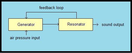
The simplest possible generic physical model of an organ flue pipe (but not that used by Viscount) is shown in Figure 1.
Figure 1. Coupled flue pipe model
The feedback loop represents the intimate coupling which exists between the generator or oscillator and the resonator as described in reference [5]. The generator is the oscillating air jet at the pipe mouth and the resonator is the pipe body sitting above it. If there were no feedback, nothing would happen - the pipe could not speak. However, when the pipe is in a normal speaking condition, an air pressure impulse appears at the flue slit formed between the languid and the lower lip when the pipe valve opens. This partly travels up the resonator and partly dissipates into the atmosphere at large. When the travelling impulse reaches the top of the pipe it is partially reflected downwards and then it affects the air jet at the mouth in a way which maintains its oscillation. In turn, the oscillating jet flips an impulse back up the pipe again and the cycle repeats indefinitely. Therefore the generator and resonator are tightly coupled and this feature has to be incorporated in a complete physical model of the pipe.
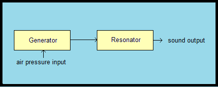
The flue pipe representation used in the physical model described in the Viscount patent, highly simplified in the same way as above, is shown in Figure 2.
Figure 2. Uncoupled flue pipe model
Here there is no feedback loop between the generator and resonator, thus the model is an uncoupled one. In fact the diagram at this basic level now represents simulation by subtractive synthesis (an oscillator followed by a filter) as much as it represents physical modelling. Therefore it is pertinent to enquire how the modelled pipe can emit sound in the absence of feedback. The answer is simply because the generator described in the patent is an independent free-running entity which feeds the resonator for as long as a key is held, though it does not relate in structural modelling terms to anything found in real musical instruments. Like all other electronic organs, the 'generator' functional block models the generated signal rather than the structure within the instrument. On the other hand, and uniquely to Viscount, the resonator does employ conventional physical modelling principles. So although the model in Figure 2 is not a complete physical model of a real flue pipe, the simplifications lead to some important practical advantages according to the patent.
The main advantage is said to lie in the ease with which the frequency of the emitted sound can be tightly defined. It is essential for a musical instrument to be well in tune, and this means its notes should be tuned to an accuracy approaching 0.01% of the exact value, at least at the higher pitches [14]. Otherwise there will be noticeable and more or less objectionable beats between the various pipes in an organ which are meant to be tuned to the same frequency. Therefore it is important to be able to set the frequency of an oscillator in a physical model of an organ to the same order of precision, and to do it rapidly in real time as the instrument is being played.
The patent argues that a problem with the coupled model (Figure 1) is that the mathematics describing its operation is both complicated and nonlinear, and deriving sufficiently exact solutions to the equations requires a lot of computer power. This can perhaps be provided when simulating monophonic orchestral instruments, but when simulating the organ the high polyphony demand (typically between 256 and 512 in a digital organ of any pretension) calls for very efficient hardware and software if the system is to run in real time. At the current state of the art this means that with many copies of a coupled pipe model, all of which might be running simultaneously, the patent implies that it would be impossible to solve the equations to the necessary degree of precision. In other words it would not be practical to provide sufficient computing power at a reasonable cost. Therefore it would be unfeasible to calculate values in advance for the oscillator constants in a coupled physical model which correspond exactly to the desired frequency. Hence Viscount's solution, which employs a simplified model with an uncoupled oscillator whose frequency can be set easily and near-instantaneously to an arbitrarily high precision.
It can be argued that an uncoupled model is nevertheless more or less satisfactory for simulating organ pipes, though this would not be so for orchestral instruments. This is because, unlike an orchestral wind instrument played by a person, the sound emitted by an organ pipe cannot vary much during its sustain phase, making the organ perhaps the easiest musical instrument of all to simulate at the level of an individual pipe. Hence there is arguably little need for a complete, sophisticated physical model to describe the operation of the pipe during most of the time it is speaking. Only during the transient attack and release phases is a coupled model desirable because then the sound is changing rapidly, and the changes are driven entirely by the nonlinear dynamics of generator-resonator coupling. An attack transient is emitted by a pipe while its initially anharmonic partials (which characterise the resonator) are being pulled into phase-lock to become the exact harmonics heard during the sustain phase. Without a coupled physical model these effects have to be simulated another way, and Viscount's method will be described later.
The simple diagram in Figure 2 can tell us nothing more about the Viscount system, so as the next step it will be useful to expand it somewhat.
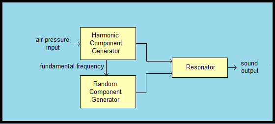
Figure 3. Top level block diagram of Viscount's flue pipe model
Figure 3 is a top level block diagram of their system, showing that the generator block in Figure 2 actually consists of two components. The Harmonic Component Generator produces the fundamental frequency (pitch tone) of the pipe currently being simulated together with a plentiful retinue of harmonics. These do not simulate the frequency spectrum of the sound emitted by the pipe directly. Rather, they simulate the spectrum generated by the oscillating air jet at the mouth which then excites the resonator. One never hears this intermediate sound in isolation from a real pipe of course. The Random Component Generator (called Aleatory Component Generator in the patent) adds an element of noise to the sound but in a complicated and time-varying manner. Its most important function is to generate the attack transient, and for this it requires the fundamental frequency of the pipe. This is fed to it as a sine wave from the Harmonic Component Generator as shown. The outputs from both of these blocks then pass into the resonating body of the pipe, which filters the spectrum of harmonics and the noise to become the sound heard from the loudspeakers of the system.
It has been mentioned already that in a digital organ there will be many identical copies of the organ pipe model sketched in this diagram. The number equals the polyphony figure of the instrument, which indicates the maximum number of simulated organ pipes which can speak simultaneously. When a note is keyed several independent models are assigned to it, the exact number depending on how many stops are drawn. For each copy of the model a large number of parameters are initialised, one of which is the correct oscillator frequency for each 'pipe', and then the corresponding sound emerges from one or more loudspeakers. All of this is under software control and it happens instantaneously as far as the player is concerned.
The model is implemented entirely in the time domain, and in this regard it is similar to sampled sound synthesis. No frequency domain processing is used, such as the harmonic spectra and inverse Fourier transforms involved in additive synthesis. Thus signals are represented as discrete digital samples which propagate through the system at a constant sample (clock) rate. The symbol z -1 which appears in some diagrams in the patent confirms this - it means a delay of one sample period. However it is not known what sample rate might actually be used as the patent makes no mention of it, nor the possible software and hardware environments on which the system could be hosted in practice. Likewise, information on bit depth (the number of bits per sample) and whether the signals are synthesised monaurally or in stereo are not discussed. It is well known that these parameters determine sound quality. Other digital music products usually synthesise the signal to at least CD quality, namely in stereo with a sample rate of 44.1 kHz and 16 bits per sample, though often this is exceeded today.
The three blocks in Figure 3 will now be described in greater detail.
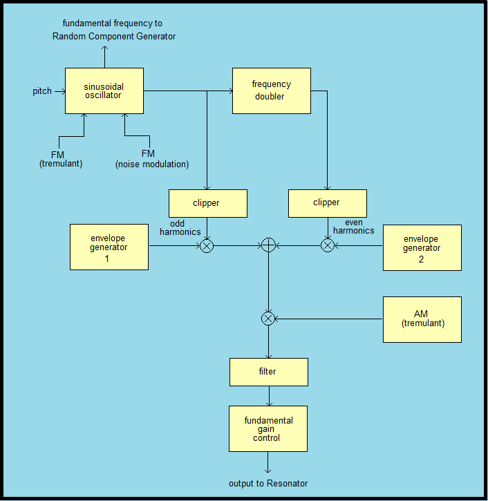
The Harmonic Component Generator is shown in block diagram form in Figure 4. This is a simplified version of Figure 3 in the patent document together with elements of some others.
Figure 4. Harmonic Component Generator
When a note is keyed a Note On event is initiated elsewhere in the system, initialising the software registers controlling the sinusoidal generator such that it outputs a sine wave at the corresponding pitch frequency. This is also the fundamental frequency of the harmonic retinue which will be generated by this module. The sine wave is also sent to the Random (Aleatory) Component Generator for purposes which are described later. While the generator is running, that is while a simulated pipe continues to sound during its sustain phase, two further inputs modulate its frequency. One is derived from a low frequency oscillator (LFO) which is presumed to be part of a tremulant model, though this word does not appear in the patent. The other randomly and continuously modulates the frequency by a small amount. This simulates the frequency dither which real organ pipes exhibit due to air turbulence and similar effects. The sine wave is then amplified and clipped so it becomes a square wave, which contains all the odd-numbered harmonics including the fundamental frequency.
The sine wave is also fed to a frequency doubler whose output is similarly clipped, providing a square wave as before but at twice the frequency. The two square waves are subsequently summed. This technique provides the second harmonic relative to the pitch frequency plus a retinue of other even-numbered harmonics, all of which would otherwise be missing. However if the double-frequency sine wave were symmetric about the zero line before clipping, some of the even harmonics in the composite (summed) waveform would still be omitted such as the 4th, 8th, 12th, etc. This problem could be mitigated by clipping the sine wave asymmetrically, thereby generating a pulse train with a mark:space ratio different to the 1:1 ratio of a square wave (but even then some harmonics will still be absent, though fewer than in the former case). It is not known whether asymmetrical clipping is employed however. It is also possible that signal power at the missing harmonic frequencies might be inserted later in the system by nonlinear filtering, as described presently.
Before they are summed, both the odd and even harmonic waveforms are modulated in amplitude by independent envelope generators. These each generate a five-segment envelope similar to that of a conventional four-segment ADSR (Attack, Decay, Sustain, Release), except that the 'attack' segment consists of two sections rather than one. The envelopes are initiated by the same Note On event which also initiates the sine wave generator.
One reason for processing the odd and even harmonics separately thus far might be because many organ pipes generate different proportions of odds to evens at the mouth, a behaviour which is under the control of the voicer to some extent. By varying the angle at which the air jet hits the upper lip by raising or lowering the languid (or pushing the upper lip of a metal pipe inwards), the effective mark:space ratio of the pulse train delivered from the jet to the resonator can be varied. If the ratio gets close to 1:1, the waveform becomes similar to a square wave and then it has relatively weak even harmonics. This happens automatically in most wooden pipes because of their mouth geometry, and it contributes to the characteristically hollow sound of wood flutes even if the pipes are open rather than stopped [6].
In Viscount's generator, the ability to control the ADSR envelopes of the odd and even harmonics independently can presumably also be used to help create an attack transient in which the even harmonic amplitudes rise faster than the odds when a note is keyed. This often happens with real principals (diapasons) and it is partly responsible for the characteristic chiff they emit, especially when voiced using Baroque techniques. These examples are not mentioned in the patent but they serve to illustrate the potentially rich voicing repertoire of this generator system.
The composite summed waveform is next amplitude modulated by the same LFO which modulates the frequency of the sinusoidal oscillator. Therefore the relative proportions of FM and AM produced by the tremulant are potentially under software control for each note of every stop.
Following this, there is a processing block labelled 'filter' in Figure 4. Referring to Figure 3 in the patent it can be seen that this actually comprises two filters, one of which is linear and the other nonlinear. The linear filter applies a programmable form of 'shading' to the harmonic amplitudes across the spectrum. The nonlinear one employs a cubic law with programmable constants, which in effect distorts the waveform. This filter might therefore introduce signal power at those even-numbered harmonics where it would otherwise have been absent, as mentioned previously. The functions of these filters are not elaborated upon in the patent, however.
The final processing block in the Harmonic Component Generator module is called 'fundamental gain control' here, though this term is not used in the patent. Figure 3 in the patent expands the content of this block and explains how it is used to control signal power at the fundamental frequency relative to that in the remainder of the spectrum. This is a voicing parameter exploited in Viscount's CM-100 product where it is called 'character' [15]. It also appears in the 'Physis - The Editor' voicing utility in recent instruments [16].
The Random Component Generator (called Aleatory Component Generator in the patent) is complicated not only at the signal flow level but also in terms of the functions it performs. Therefore the description here is simplified. Its main function is to generate the attack transient when a note is keyed, but it also introduces low level band limited noise into the sound of a simulated pipe during its sustain phase. A block diagram of the complete processing module is shown here at Figure 5, which is a simplified and combined version of Figures 10 and 11 in the patent.
Figure 5. Random Component Generator
A sine wave at the fundamental (pitch) frequency of the note keyed is supplied from the Harmonic Component Generator to an amplifier and clipper, thereby creating a square wave. This is high pass filtered and then rectified so that the negative-going parts of the waveform are removed. A spiky pulse train at the fundamental frequency is thereby generated of the form shown in the diagram, and in the patent this waveform is called 'RATE'. An attack envelope in the form of a descending ramp is applied to the signal, which progressively attenuates its level during the attack transient phase of the sound. However the signal is not cut off completely, thus it continues at a lower level while the note is sustained and then into the release phase. The RATE signal is next applied to a rather complicated processing module called the 'Noise Box' whose internal structure is neither shown nor discussed here, though further details are available in Figures 11 and 12 of the patent document. All we need to know is what the Noise Box does, and this will be described at a simplified level.
Besides the RATE input, the Noise Box is also supplied with a noise signal which is assumed here to have the spectral characteristics of pink noise (i.e. with a spectrum power slope of -3 dB/octave). The patent shows that this signal is derived from a white noise generator via a low pass filter. It is assumed that the filter is of first order, thereby creating pink noise, though this is not defined in the patent.
Figure 6. Diagrammatic representation of the spectrum of the signal output from the Noise Box for a hypothetical constant amplitude RATE input
Firstly let us assume the RATE input to the Noise Box is maintained constant at its peak amplitude instead of being a periodic pulse train, though this 'DC level' would not arise in normal operation. In this hypothetical situation the Noise Box would appear to generate several peaks of band-limited noise sitting above the broader pink noise continuum, as suggested by the sketch in Figure 6. The centre frequencies of the peaks can be placed anywhere under software control, and the patent says they are intended "to imitate the frequency response of a resonator with irregular geometry, such as the portion of space of the organ pipe immediately inside the mouth". In practice however, the Q-factors of the resonances, and therefore their amplitudes and bandwidths above the noise continuum, are controlled dynamically by the instantaneous amplitude of the RATE signal. The peaks are highest and sharpest when RATE assumes its maximum value as just described, and smallest and broadest when it is at a minimum. Because of the spiky nature of the RATE pulse train, this means that the resonant peaks only appear at maximum amplitude during a small fraction of the pulse period (although there is a nonlinear process called 'Rate Limiter' described in the patent which might broaden and smooth the pulse shape somewhat). Thus for most of each inter-pulse period the spectrum peaks are attenuated, though probably not entirely absent. This behaviour corresponds to the design brief in the patent which says that "by analysing the spectrogram of the individual wave periods of a sample [of an organ pipe sound] and using a much finer time resolution than a wave period, it can be noted that a large percentage of sound energy concentrates in a time interval much shorter than the period, always situated in the same position along the wave period".
Consequently the attack transient waveform seems to be modelled essentially as a sequence of structured noise bursts, the structure arising from the particular frequencies chosen to simulate certain resonances of a particular pipe as mentioned above. They are not, presumably, the chief resonances of the pipe body because these are modelled elsewhere in the resonator module of the system (described below). The noise burst sequence is periodic at the fundamental frequency of the simulated pipe, and during each period the peaks are in effect modulated in amplitude on top of a broader continuum of pink noise by virtue of the process just described. As shown in Figure 5 above, this composite signal is further amplitude-modulated by a standard ADSR envelope. However this is not yet the attack transient which is heard because it then passes to the resonator module where it will be filtered further by the natural resonances of the pipe body.
The system also appears to offer a capability to add a programmable level of broadband noise during the remainder of the sounding epoch of the pipe by suitably adjusting the various attack/release envelopes, which control the amplitude of the noise signal as a function of time after the Note On event.
As shown earlier in Figure 3, the outputs of the Harmonic Component Generator and the Random (Aleatory) Component Generator feed the resonator module which models the pipe body sitting above the mouth. A description of the technique of waveguide synthesis for modelling a resonator is given elsewhere on this website at reference [10], and it can be compared with that used by Viscount shown in Figure 15 of the patent. An important feature of a real organ pipe is the anharmonicity of its natural resonances, meaning that their frequencies are not harmonically related. This is an important part of the tone-forming process in organ pipes as explained in references [5], [11] and [12]. Viscount have incorporated this in their resonator model by means of an all-pass filter which, according to the patent, "modifies the total phase delay of the closed cycle formed by the elements (46) ... (54) in a selective way with respect to the frequency, in order to make the resonance of the linear resonator (12) realistically inharmonious". (The numbers in this quotation relate to corresponding entities in diagrams in the patent). Presumably one should construe 'inharmonious' as 'anharmonic'. One also assumes the all-pass filter constants are programmable to enable the degree of anharmonicity to be related to pipe dimensions as with real pipes - the wider the pipe in relation to its speaking length (i.e. the larger its scale), the more its resonances diverge from an harmonic relationship and vice versa. However the patent is silent about the details of the filter actually implemented, therefore further analysis of this aspect of the model is not possible.
Another important feature of real pipes is the phase reversal experienced by the travelling acoustic wave when it reaches the top of an open pipe. The same thing happens at the mouths of both open and stopped pipes, which are also open acoustically. The wave is partially reflected at both these points in an open pipe owing to the sudden change in acoustic impedance, and it also reverses in phase - a positive pressure impulse changes into one of negative pressure on reflection and vice versa. However, if the pipe is closed at the top by a stopper there is no longer a phase change on reflection there, whereas that at the mouth remains as before. This behaviour must be incorporated in a physical model of the pipe, and in Viscount's model it appears to be catered for by the arithmetical sign (plus or minus) introduced by the element labelled 'TFBK' in Figure 15 of the patent. It is essential to include the phase effect because it is responsible for the tonal difference between open and stopped pipes in which the even-numbered harmonics are attenuated in the latter. The issues are explained in more detail in references [5] and [10] elsewhere on this site.
Thus the harmonic spectrum of the sound emitted by the simulated pipe in its sustain phase depends firstly on the spectrum of the signal arriving from the Harmonic Component Generator, and secondly on the subsequent spectral shaping applied to it by the resonances of the pipe body model and whether the resonator partially suppresses the even harmonics. The pipe body acts like an asymmetrical comb filter, the asymmetry arising because the 'teeth' of the comb are not equally spaced in frequency. This reflects the anharmonicity of the pipe resonances. In Viscount's system the signal produced by the generator and the subsequent filtering action of the pipe are independent because of the absence of coupling between the generator and resonator - one does not affect the other. In a real pipe they are not independent because of the strong coupling which exists between the generator and resonator as mentioned earlier.
A significant structural difference between the resonator model adopted by Viscount and that discussed in reference [10] concerns the delay line or 'waveguide' which simulates the transit time of an acoustic wave up and down the pipe. In the patent it appears to consist of a single untapped line, whereas in reference [10] two separate lines are considered. This latter configuration enables sound emission from both the top and the mouth of an open pipe to be modelled separately, and then combined as desired before sending the result to a loudspeaker. In fact the two sound sources can with advantage be radiated from separate loudspeakers if a physically large open pipe is being modelled, leading (for example) to more realistic spatial simulations of the flue basses in a building. It is difficult to see how this could be done in the Viscount model. Formally, the difference relates to the acoustic monopole radiation which characterises stopped pipes compared with the dipole radiation of open pipes. It is no mere academic nicety because it explains why basses derived from stopped pipes are on the whole less satisfactory than those using full length pipes. The latter generally suffer less from the acoustic 'dead zones' in a building which can result from using stopped basses.
This article has discussed the patent on the physical modelling synthesis of organ flue pipes granted to Viscount International SpA. It has confined itself solely to the description in the patent specification rather than speculating on technical aspects of Viscount products, which might differ.
It was shown that the modelling concept described in the patent specification departs from that usually discussed in the literature in that there is no coupling or feedback between the sound generating and resonating elements of the simulated pipe. Moreover, the generator model described in the patent does not correspond to the type of nonlinear oscillator normally assumed when modelling flue pipes and similar wind instruments. Instead it models the acoustic excitation signal applied to the resonator rather than modelling the oscillator itself for reasons which are described in the patent. On the other hand, the resonator is modelled according to generally accepted physical modelling principles relating to waveguide synthesis, and this makes the system unique to Viscount as far as digital organs are concerned.
The model is rich in terms of the number of parameters which can be adjusted to achieve the sound desired. Virtually everything which can be adjusted seems to be software-adjustable, leading to a potentially wide range of voicing options.
The article is offered to expand some technical aspects of an innovative and novel approach to digital music synthesis, and to make them more accessible to a wider and less specialist audience than that targeted by the patent itself.
1. "Digital Organs Today", C E Pykett, Organists' Review, November 2009. Also available as an article on this website (read).
2. "Method and electronic device used to synthesise the sound of church organ flue pipes by taking advantage of the physical modelling technique of acoustic instruments", United States patent US7442869, 28 October 2008.
www.google.com/patents/US7442869 (accessed 6 April 2016)
The assignee of the patent is Viscount International SpA and the inventor is Carlo Zinato.
3. "Multiplexing System for Selection of Notes and Voices in an Electronic Musical Instrument", US Patent 3610799, 5 October 1971.
4. "Digital Generator for Musical Notes", UK Patent 1580690, 3 December 1980.
5. "How the Flue Pipe Speaks", C E Pykett, 2001.
6. "The Tonal Structure of Organ Flute Stops", C E Pykett, 2003.
7. "The Tonal Structure of Organ Principal Stops", C E Pykett, 2006.
8. "The Tonal Structure of Organ String Stops", C E Pykett, 2012.
9. "A Second in the Life of a Violone", C E Pykett, 2005.
10. "Physical Modelling in Digital Organs", C E Pykett, 2009.
11. "The Physical Modelling of Organ Flue Pipes - a Complete Picture", C E Pykett, 2013.
12. "The End Corrections, Natural Frequencies, Tone Colour and Physical Modelling of Organ Flue Pipes", C E Pykett, 2013.
13. "The Effect of Organ Pipe Scales on their Harmonic Spectra", C E Pykett, 2016.
14. The tuning tolerance figure of 0.01% quoted in the article arises from considering an organ pipe with a fundamental frequency of about 1 kHz, corresponding roughly to the note C5 on an 8 foot stop (C5 is the octave below top C on a five-octave keyboard). If another pipe had a frequency 0.01% away from this figure, the two pipes would beat (at one beat in ten seconds) if they sounded together. This would usually be considered acceptable, but whether or no, their mutual detuning could not be permitted to drift much beyond the 0.01% figure because, at higher frequencies, the beats would be correspondingly faster and they would become unacceptable.
15. See www.organworks.com/support/cm100%20Wicks%20Advanced.pdf (accessed 2 April 2016)
16. See www.viscountinstruments.us/physis-the-editor.html ('Parameters Edit' screen) (accessed 2 May 2016)
|